Mitsubishi Outlander XL. Manual - part 244


  Index      Mitsubishi     Mitsubishi Outlander XL - service repair manual 2007 year


Search            


Content   ..  242  243  244  245   ..


Mitsubishi Outlander XL. Manual - part 244


DIAGNOSIS

Required Special Tools:

MB991958: Scan Tool (M.U.T.-III Sub Assembly)

MB991824: V.C.I.

MB991827: USB Cable

MB991910: Main Harness A

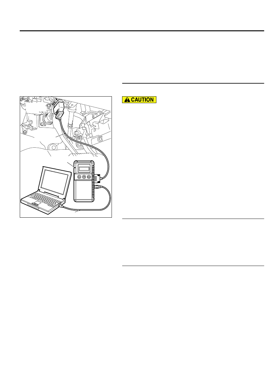
STEP 1. Using scan tool MB991958, check data list item 6:
Engine Coolant Temperature Sensor.

ZC501967

AC404789

ZC5019680000

MB991824

MB991827

MB991910

Data link

connector

To prevent damage to scan tool MB991958, always turn the
ignition  switch  to  the  "LOCK"  (OFF)  position  before
connecting or disconnecting scan tool MB991958.

(1)

Connect scan tool MB991958 to the data link connector.

(2)

Turn the ignition switch to the "ON" position.

(3)

Set scan tool MB991958 to the data reading mode for item
6, Engine Coolant Temperature Sensor.

The engine coolant temperature and temperature shown
with the scan tool should approximately match.

(4)

Turn the ignition switch to the "LOCK" (OFF) position.

Q:Is the sensor operating properly?

YES:

 It can be assumed that this malfunction is

intermittent. Refer to GROUP 00, How to Use
Troubleshooting/Inspection Service Points - How to Cope
with Intermittent Malfunctions P.00-15.

NO:

 Go to Step 2.

STEP 2. Check harness connector B-09 at the engine
coolant temperature sensor and harness connector B-10 at
the ECM for damage.

Q:Is the harness connector in good condition?

YES:

 Go to Step 3.

NO:

 Repair it. Refer to GROUP 00E, Harness Connector

Inspection P.00E-2. Then go to Step 5.

STEP 3. Check the engine coolant temperature sensor.

(1)

Disconnect  the  engine  coolant  temperature  sensor
connector B-106.

(2)

Remove the engine coolant temperature sensor.

MULTIPORT INJECTION SYSTEM (MFI) <DIAGNOSIS>

13Ab-171

DIAGNOSTIC TROUBLE CODE PROCEDURES

ZK603214AA00

(3)

With  the  temperature  sensing  portion  of  engine  coolant
temperature sensor immersed in hot water, check resistance.

Standard value:

14 - 17 kΩ [at -20°C (-4°F)]
5.1 - 6.5 kΩ [at 0°C (32°F)]
2.1 - 2.7 kΩ [at 20°C (68°F)]
0.9 - 1.3 kΩ [at 40°C (104°F)]
0.48 - 0.68 kΩ [at 60°C (140°F)]
0.26 - 0.36 kΩ [at 80°C (176°F)]

ZK603215AA00

(4)

Apply  3M™  AAD  part  number  8731  or  equivalent  on  the
screw section of the engine coolant temperature sensor.

(5)

Install the engine coolant temperature sensor, and tighten to
the specified torque.

Tightening torque: 29 ± 10 N·m (22 ± 7 ft-lb)

Q:Is the measured resistance at the standard value?

YES:

 Replace the engine coolant temperature sensor. Then

go to Step 5.

NO:

 Go to Step 4.

STEP 4. Check for harness between the engine coolant
temperature sensor connector B-09 and the ECM connector
B-10.

(1)

Disconnect  the  engine  coolant  temperature  sensor
connector B-09 and the ECM connector B-10.

ZK603217

1

2

16 15 14 13 12 11 10 9 8 7 6 5 4 3

2

1

32 31 30 29 28 27 26 25 24 23 22 21 20 19 18 17

48 47 46 45 44 43 42 41 40 39 38 37 36 35 34 33

64 63 62 61 60 59 58 57 56 55 54 53 52 51 50 49

AA00

B-10 harness
connector:
component side 

B-09 harness
connector:
component side 

(2)

Measure  the  resistance  between  the  engine  coolant
temperature sensor connector B-09 and the ECM connector
B-10.

a
.

Connector  B-09  (terminal  No.  1)  and  Connector  B-10
(terminal No. 26).

b
.

Connector  B-09  (terminal  No.  2)  and  Connector  B-10
(terminal No. 27).

Should be less than 2 ohms.

Q:Is the harness wire in good condition?

YES:

 Replace the ECM. When the ECM is replaced, register

the ID code. Refer to GROUP 42B, ID Code Registration
Judgment Table <Vehicles with KOS> P.42B-12or GROUP
42C, ID Code Registration Judgment Table <Vehicles with
WCM> P.42C-8. Then go to step 5.

NO:

 Repair it. Then go to Step 5.

STEP 5. Test the OBD-II drive cycle.

(1)

Carry out a test drive with the drive cycle pattern. Refer to
Diagnostic  Function  -  OBD-II  Drive  Cycle  -  Pattern  24  P.
13Ab-8.

13Ab-172

MULTIPORT INJECTION SYSTEM (MFI) <DIAGNOSIS>

DIAGNOSTIC TROUBLE CODE PROCEDURES

(2)

Check the diagnostic trouble code (DTC).

Q:Is DTC P0118 set?

YES:

 Replace the ECM. When the ECM is replaced, register

the ID code. Refer to GROUP 42B, ID Code Registration
Judgment Table <Vehicles with KOS> P.42B-12or GROUP
42C, ID Code Registration Judgment Table <Vehicles with
WCM> P.42C-8.

NO:

 It can be assumed that this malfunction is

intermittent. Refer to GROUP 00, How to Use
Troubleshooting/Inspection Service Points How to Cope
with Intermittent Malfunctions P.00-15.

MULTIPORT INJECTION SYSTEM (MFI) <DIAGNOSIS>

13Ab-173

DIAGNOSTIC TROUBLE CODE PROCEDURES

DTC P0122: Throttle Position Sensor (Main) Circuit Low Input

M11310100182USA0000010000

ZK602837

1

2

3 4 5 6 7 8 9 10 11 12 13 14 15 16

17 18 19 20 21 22 23 24 25 26 27 28 29 30 31 32

33 34 35 36 37 38 39 40 41 42 43 44 45 46 47 48

49 50 51 52 53 54 55 56 57 58 59 60 61 62 63 64

6

1 2 3 4 5

5 V

12

5

10

13

4

3

THROTTLE POSITION SENSOR (MAIN) CIRCUIT

THROTTLE POSITION
SENSOR (MAIN)

B-10

HALL IC

AA00

YELLO

W

-GRA

Y

YELLO

W

-RED

GRA

Y

-RED

ENGINE
CONTROL
MODULE

B-08

(MU805200)

ZK603599 AA00

Throttle body assembly
(incorporating throttle
position sensor)

B-08 (B)

Connector: B-08

ZK603591

ECM

B-10 (GR)

Connector: B-10

AA00

13Ab-174

MULTIPORT INJECTION SYSTEM (MFI) <DIAGNOSIS>

DIAGNOSTIC TROUBLE CODE PROCEDURES


Content   ..  242  243  244  245   ..