Mitsubishi Outlander XL. Manual - part 238
ZK603210AA00
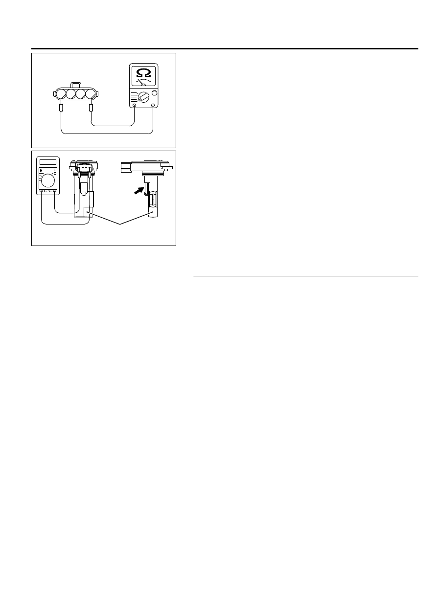
1
2
3
4
Intake air temperature
sensor connector
(3)
Measure the resistance between intake air temperature
sensor side connector terminal No. 1 and No. 4.
ZK603211AA00
Mass airflow
sensor
Intake air
temperature
sensor
(4)
Measure resistance while heating the sensor using a hair
drier.
Standard value:
13 - 17 kΩ [at -20°C (-4°F)]
5.3 - 6.7 kΩ [at 0°C (32°F)]
2.3 - 3.0 kΩ [at 20°C (68°F)]
1.0 - 1.5 kΩ [at 40°C (104°F)]
0.56 - 0.76 kΩ [at 60°C (140°F)]
0.30 - 0.45 kΩ [at 80°C (176°F)]
Q:Is the measured resistance at the standard value?
YES:
Replace the mass airflow sensor. Then go to Step 3.
NO:
Go to Step 3.
STEP 3. Test the OBD-II drive cycle.
(1)
Carry out a test drive with the drive cycle pattern. Refer to
Diagnostic Function - OBD-II Drive Cycle - Pattern 8 P.
13Ab-8.
(2)
Check the diagnostic trouble code (DTC).
Q:Is DTC P0111 set?
YES:
Replace the ECM. When the ECM is replaced, register
the ID code. Refer to GROUP 42B, ID Code Registration
Judgment Table <Vehicles with KOS> P.42B-12or GROUP
42C, ID Code Registration Judgment Table <Vehicles with
WCM> P.42C-8.
NO:
It can be assumed that this malfunction is
intermittent. Refer to GROUP 00, How to Use
Troubleshooting/Inspection Service Points How to Cope
with Intermittent Malfunctions P.00-15.
MULTIPORT INJECTION SYSTEM (MFI) <DIAGNOSIS>
13Ab-147
DIAGNOSTIC TROUBLE CODE PROCEDURES