Content .. 1289 1290 1291 1292 ..
Mitsubishi Outlander XL. Manual - part 1291
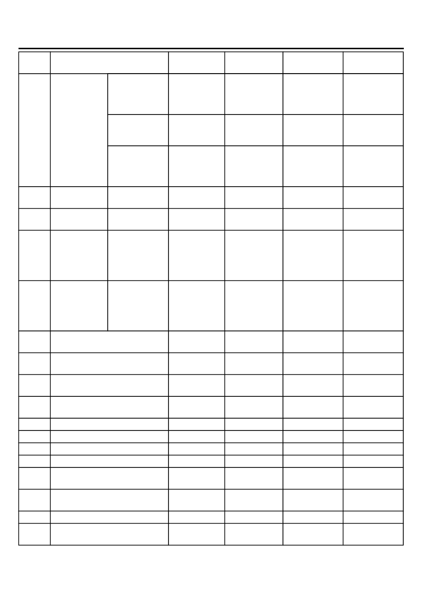
DTC
Item
Brake
warning light
ABS warning
light
ASC
ON
indicator light
ASC
OFF
indicator light
Abnormality in
lateral
G-
sensor output
voltage
OFF
OFF
ON
ON
Abnormality in
yaw rate sensor
output voltage
OFF
OFF
ON
ON
Abnormality in
G and yaw rate
sensor supply
voltage
OFF
⦆
OFF (FWD)
⦆
ON (AWD)
ON
ON
C2111 Sensor power
supply circuit
Low input
OFF
ON
ON
ON
C2112 Sensor power
supply circuit
High input
OFF
ON
ON
ON
C2114 Abnormality in
G and yaw rate
sensor
operation
voltage
Low
voltage
(6.5 ± 0.5 V or
less)
OFF
⦆
OFF (FWD)
⦆
ON (AWD)
ON
ON
C2115 Abnormality in
G and yaw rate
sensor
operation
voltage
High
voltage
(18.0 ± 1.0 V or
more)
OFF
⦆
OFF (FWD)
⦆
ON (AWD)
ON
ON
C123A Abnormality
in
sensor
calibration
OFF
ON
ON
ON
C1219 Abnormality in steering wheel
sensor signal
OFF
OFF
ON
ON
C121A Steering wheel sensor neutral
point not learned
OFF
Flashing (2 Hz) OFF
OFF
C2205 Internal abnormality in steering
wheel sensor
OFF
OFF
ON
ON
C1608 Implausible diagnosis data
OFF
OFF
OFF
OFF
U0001 Bus-off
OFF
OFF
OFF
OFF
U0100 Engine time-out error
OFF
OFF
OFF
OFF
U0101 A/T time-out error
OFF
OFF
OFF
OFF
U0114
*4
AWD-ECU time-out error
OFF
OFF
OFF
OFF
U0126 Steering wheel sensor time-out
error
OFF
OFF
OFF
OFF
U0141 ETACS time-out error
OFF
OFF
OFF
OFF
U0125 G and yaw rate sensor message
time-out error/message error
OFF
⦆
OFF (FWD)
⦆
ON (AWD)
ON
ON
35C-18
ACTIVE STABILITY CONTROL SYSTEM (ASC)
CONSTRUCTION DESCRIPTION