Content .. 1258 1259 1260 1261 ..
Mitsubishi Outlander XL. Manual - part 1260
System
Objective / Function
Composition parts
Controls air-fuel ratio of air-fuel
mixture to become theoretical air-
fuel ratio (about 14.7), which is
when
the
3-way
catalytic
converter's cleaning performance
is best. It also controls optimum
fuel supply based on coolant
temperature, driving conditions
etc.
Catalytic
converter
Decrease of CO, HC and NOx
It facilitates oxidation of CO and
HC and reduction of NOx so that
all 3 component gases are
cleaned simultaneously.
Monolith catalyst
HC
trap
catalytic
converter
<California>
HC decrease
During cold operation of engine,
exhaust
HC
is
temporarily
absorbed. And then Exhaust HC is
released
when
temperature
reaches to level at which catalyst
is activated. This allows HC to be
reduced.
Monolith catalyst
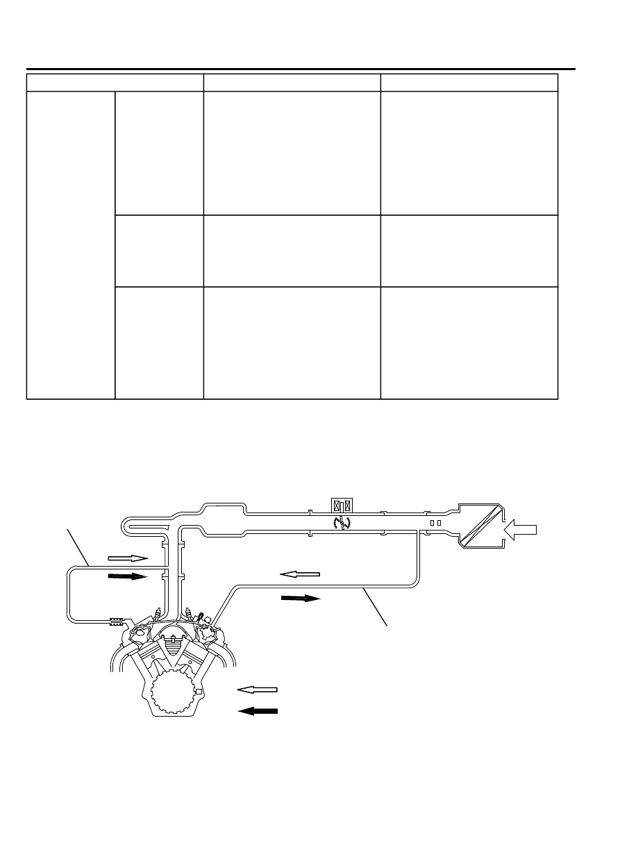
CRANKCASE VENTILATION SYSTEM
M21701000004USA0000010000
ZK602752 AA00
Ventilation hose
Breather hose
Air cleaner
PCV valve
Flow of blow-by gas and clean air (low load area)
Flow of blow-by gas (high load area)
17c-4
EMISSION CONTROL
CRANKCASE VENTILATION SYSTEM