Mitsubishi Outlander XL. Manual - part 1198


  Index      Mitsubishi     Mitsubishi Outlander XL - service repair manual 2007 year


Search            


Content   ..  1196  1197  1198  1199   ..


Mitsubishi Outlander XL. Manual - part 1198


Q:Is the check result satisfactory?

YES:

 The procedure is complete.

NO:

 Replace the A/C-ECU.

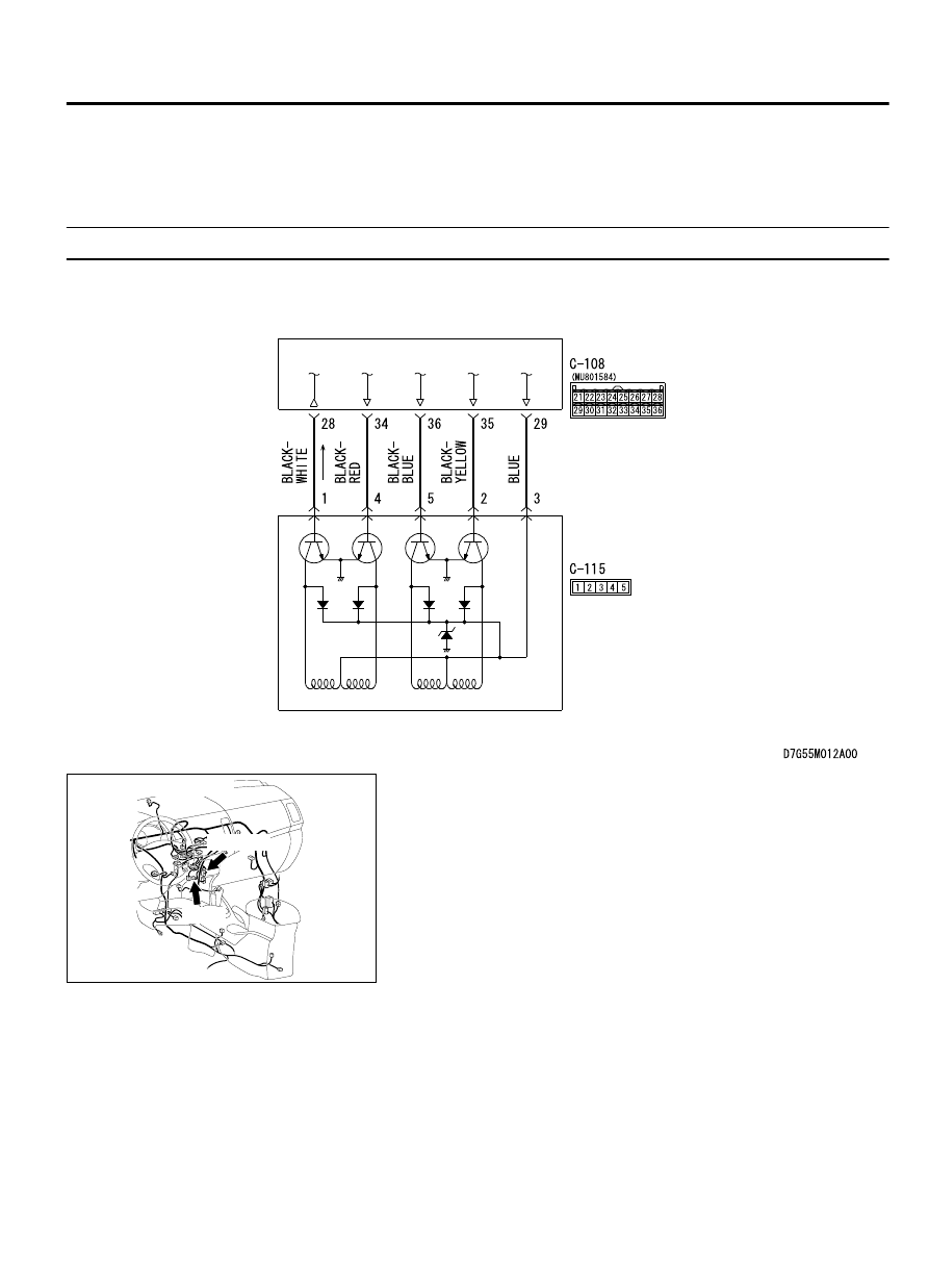
INSPECTION PROCEDURE 7: A/C Outlet Air Temperature does not Increase

M15502000958USA0000010000

Air Mixing Damper Control Motor Circuit 

AIR MIXING
DAMPER CONTROL
MOTOR

A/C-ECU

ZC6008760040

Connector: C-08, C-115

C-108 (B)

C-115

CIRCUIT OPERATION
If the air outlet temperature cannot be adjusted, the
air mixing damper control motor circuit may be failed.

TROUBLESHOOTING HINTS

Malfunction of the air mixing damper control motor

Malfunction of the A/C-ECU

Damaged harness wires or connectors

DIAGNOSIS

Required Special Tools:

MB991223: Harness Set

MB992006: Extra Fine Probe

MB991958: Scan Tool (M.U.T.-III Sub Assembly)

MB991824: V.C.I.

AIR CONDITIONING

55A-83

MANUAL A/C DIAGNOSIS

MB991827: M.U.T.-III USB Cable

MB991910: M.U.T.-III Main Harness A

STEP 1. Using scan tool MB991958, read the diagnostic
trouble code.
Check if an A/C-ECU DTC is set.

(1)

Connect scan tool MB991958 to the data link connector.

(2)

Turn the ignition switch to the "ON" position.

(3)

Check if the DTC is set.

(4)

Turn the ignition switch to the "LOCK" (OFF) position.

Q:Is the check result satisfactory?

YES:

 Go to Step 2.

NO:

 Refer to DIAGNOSTIC TROUBLE CODE CHART P.55A-8.

STEP 2. Check air mixing damper control motor connector
C-115 and A/C-ECU connector C-108 for loose, corroded or
damaged terminals, or terminals pushed back in the
connector.

Q:Are air mixing damper control motor connector C-115 and

A/C-ECU connector C-108 in good condition?

YES:

 Go to Step 3.

NO:

 Repair or replace the connector. Refer to GROUP 00E,

Harness Connector Inspection P.00E-2. Check that the A/C
works normally.

STEP 3. Check the wiring harness between A/C-ECU
connector C-108 (terminal 29, 35, 36, 34 and 28) and air
mixing damper control motor connector C-115 (terminals 3,
2, 5. 4 and 1).

Q:Are  the  wiring  harness  between  A/C-ECU  connector

C-108  (terminal  29,  35,  36,  34  and  28)  and  air  mixing

damper control motor connector C-115 (terminals 3, 2, 5.

4 and 1) in good condition?

YES:

 Go to Step 4.

NO:

 Repair the wiring harness. Check that the A/C works

normally.

STEP 4. Replace the power transistor and check the trouble
symptom again
Check the trouble symptom again.

Q:Is the check result satisfactory?

YES:

 The procedure is complete.

NO:

 Replace the A/C-ECU.

55A-84

AIR CONDITIONING

MANUAL A/C DIAGNOSIS

INSPECTION PROCEDURE 8: Air Outlet Vent cannot be Changed.

M15502000959USA0000010000

Mode Selection Damper Control Motor Circuit

MODE SELECTION 
DAMPER CONTROL 
MOTOR

A/C-ECU

ZC600876

Connectors: C-108, C-130

C-108 (B)

C-107

CIRCUIT OPERATION
If the air outlet cannot be switched, the mode selection
damper control motor circuit may be failed.

TROUBLESHOOTING HINTS

Malfunction of the mode selection damper control
motor

Malfunction of the A/C-ECU

Damaged harness wires or connectors

DIAGNOSIS

Required Special Tools:

MB991223: Harness Set

MB992006: Extra Fine Probe

MB991958: Scan Tool (M.U.T.-III Sub Assembly)

MB991824: V.C.I.

MB991827: M.U.T.-III USB Cable

MB991910: M.U.T.-III Main Harness A

AIR CONDITIONING

55A-85

MANUAL A/C DIAGNOSIS

STEP 1. Using scan tool MB991958, read the diagnostic
trouble code.
Check if an A/C-ECU DTC is set.

(1)

Connect scan tool MB991958 to the data link connector.

(2)

Turn the ignition switch to the "ON" position.

(3)

Check if the DTC is set.

(4)

Turn the ignition switch to the "LOCK" (OFF) position.

Q:Is the check result satisfactory?

YES:

 Go to Step 2.

NO:

 Refer to DIAGNOSTIC TROUBLE CODE CHART P.55A-8.

STEP 2. Check mode selection damper control motor
connector C-107 and A/C-ECU connector C-108 for loose,
corroded or damaged terminals, or terminals pushed back
in the connector.

Q:Are  mode  selection  damper  control  motor  connector

C-107 and A/C-ECU connector C-108 in good condition?

YES:

 Go to Step 3.

NO:

 Repair or replace the connector. Refer to GROUP 00E,

Harness Connector Inspection P.00E-2. Check that the A/C
works normally.

STEP 3. Check the wiring harness between A/C-ECU
connector C-108 (terminal 29, 31, 32, 30 and 33) and mode
selection damper control motor connector C-107 (terminals
3, 2, 5. 4 and 1).

Q:Are  the  wiring  harness  between  A/C-ECU  connector

C-108 (terminal 29, 31, 32, 30 and 33) and mode selection

damper control motor connector C-107 (terminals 3, 2, 5.

4 and 1) in good condition?

YES:

 Go to Step 4.

NO:

 Repair the wiring harness. Check that the A/C works

normally.

STEP 4. Replace the power transistor and check the trouble
symptom again
Check the trouble symptom again.

Q:Is the check result satisfactory?

YES:

 The procedure is complete.

NO:

 Replace the A/C-ECU.

55A-86

AIR CONDITIONING

MANUAL A/C DIAGNOSIS


Content   ..  1196  1197  1198  1199   ..