Mitsubishi Outlander XL. Manual - part 1194


  Index      Mitsubishi     Mitsubishi Outlander XL - service repair manual 2007 year


Search            


Content   ..  1192  1193  1194  1195   ..


Mitsubishi Outlander XL. Manual - part 1194


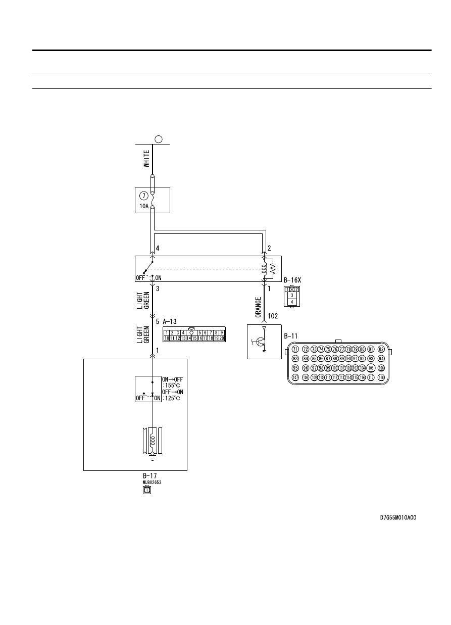
INSPECTION PROCEDURE 3: The Compressor does not Work.

M15502000919USA0000010000

A/C Compressor Assembly Circuit 

A/C
COMPRESSOR
CLUTCH RELAY

A/C
COMPRESSOR
ASSEMBLY

A/C
REFRIGERANT
TEMPERATURE
SWITCH

A/C
COMPRESSOR
CLUTCH

ENGINE-ECU

RELAY
BOX

FUSIBLE
LINK

36

AIR CONDITIONING

55A-67

MANUAL A/C DIAGNOSIS

ZC6008740004

Connector: B-17

B-17 (B)

ZC604243 0000

Connector: B-16X

B-16X

ZC6008720012

Connector: A-13

ZC6008740000

Connector: B-11

B-11 (GR)


FUNCTION
Compressor  that  recovers  the  refrigerant,  which
evaporated  in  the  evaporator  and  became  a  high-
temperature and high-pressure gas, and turns it into
liquid again.

PROBABLE CAUSES

Insufficient refrigerant

Malfunction of connector.

Malfunction of the harness (A/C compressor circuit
is open/shorted to ground)

Malfunction of the A/C pressure sensor.

Malfunction of the A/C compressor.

Malfunction of the A/C compressor clutch relay.

Malfunction of the A/C-ECU.

DIAGNOSIS

Required Special Tools:

MB991223: Harness Set

MB992006: Extra Fine Probe

MB991658: Test Harness Set

MB991958: Scan Tool (M.U.T.-III Sub Assembly)

MB991824: V.C.I.

MB991827: M.U.T.-III USB Cable

MB991910: M.U.T.-III Main Harness A

55A-68

AIR CONDITIONING

MANUAL A/C DIAGNOSIS

STEP 1. Using scan tool MB991958, diagnose the CAN bus
line.

ZC501967

AC404789

ZC5019680000

MB991824

MB991827

MB991910

Data link

connector

To prevent damage to scan tool MB991958, always turn the
ignition  switch  to  the  "LOCK"  (OFF)  position  before
connecting or disconnecting scan tool MB991958.

(1)

Connect scan tool MB991958. Refer to "How to connect the
Scan Tool (M.U.T.-III) P.55A-6."

(2)

Turn the ignition switch to the "ON" position.

(3)

Diagnose the CAN bus line.

(4)

Turn the ignition switch to the "LOCK" (OFF) position.

Q:Is the CAN bus line found to be normal?

YES:

 Go to Step 2.

NO:

 Repair the CAN bus lines (Refer to GROUP 54D,

precautions on how to repair the CAN bus lines P.54D-17).

STEP 2. Using scan tool MB991958, read the diagnostic
trouble code.
Check if an A/C-ECU DTC is set.

(1)

Connect scan tool MB991958 to the data link connector.

(2)

Turn the ignition switch to the "ON" position.

(3)

Check if the DTC is set.

(4)

Turn the ignition switch to the "LOCK" (OFF) position.

Q:Is the check result satisfactory?

YES:

 Refer to Diagnostic Trouble Code Chart P.55A-8.

NO:

 Go to Step 3.

STEP 3. Check A/C compressor assembly connector B-17
for loose, corroded or damaged terminals, or terminals
pushed back in the connector.

Q:Is  A/C  compressor  assembly  connector  B-17  in  good

condition?

YES:

 Go to Step 4.

NO:

 Repair or replace the connector. Refer to GROUP 00E,

Harness Connector Inspection P.00E-2.

AIR CONDITIONING

55A-69

MANUAL A/C DIAGNOSIS

STEP 4. Check the A/C compressor clutch operation.

ZC6020180000

Connect  the  compressor  connector  terminal  to  the  battery
positive  (+)  terminal  and  ground  the  battery’s  negative  (-)
terminal to the compressor unit. At that time, the A/C compressor
clutch should make a definite operating sound.

Q:Can  the  sound  (click)  of  the  A/C  compressor  clutch

operation be heard?

YES:

 Go to Step 5.

NO:

 Replace the compressor magnet clutch.

STEP 5. Check A/C compressor clutch relay connector
A-16X for loose, corroded or damaged terminals, or
terminals pushed back in the connector.

Q:Is A/C compressor clutch relay connector A-16X in good

condition?

YES:

 Go to Step 6.

NO:

 Repair or replace the connector. Refer to GROUP 00E,

Harness Connector Inspection P.00E-2.

STEP 6. Check the A/C compressor clutch relay continuity.

ZC603579

4

1

2

3

3

1

4

2

A/C compressor clutch relay

Follow the table below to check the A/C compressor clutch relay
for continuity.

Battery voltage

Tester
connection

Specified
condition

Not applied

3 - 4

Open circuit

Connect  terminal  2
to

 the

 positive

battery terminal

Connect  terminal  1
to

 the

 negative

battery terminal

3 - 4

Less than 2 ohms

Q:Is the A/C compressor clutch relay in good condition?

YES:

 Go to Step 7.

NO:

 Replace the A/C compressor clutch relay.

STEP 7. Check engine control module connector B-11 for
loose, corroded or damaged terminals, or terminals pushed
back in the connector.

Q:Is  engine  control  module  connector  B-11  in  good

condition?

YES:

 Go to Step 8.

NO:

 Repair or replace the connector. Refer to GROUP 00E,

Harness Connector Inspection P.00E-2.

55A-70

AIR CONDITIONING

MANUAL A/C DIAGNOSIS


Content   ..  1192  1193  1194  1195   ..