Content .. 1187 1188 1189 1190 ..
Mitsubishi Outlander XL. Manual - part 1189
Past trouble
⦆
If DTC U0154 is stored as a past trouble, carry out
diagnosis with particular emphasis on wiring and
connector(s) in the CAN bus line between the A/C-
ECU and the Occupant classification-ECU, and the
power supply system to the Occupant classification-
ECU. If the connectors and wiring are normal, and
obviously the ECU is the cause of the trouble,
replace the ECU. If in doubt, do not replace the
ECU.
NOTE:
For a past trouble, you cannot find it by
the scan tool CAN bus diagnostics even if there
is a failure in CAN bus lines. In this case,
refer to GROUP 00, How to Use Troubleshooting/
Inspection Service Points - How to Cope with
Intermittent Malfunctions P.00-15) and check
the CAN bus lines. You can narrow down the
possible cause of the trouble by referring to
the DTC, which is set regarding the CAN
communication-linked ECUs (Refer to GROUP 54D,
Explanation about the scan too CAN bus
diagnostics P.54D-10).
TROUBLESHOOTING HINTS
⦆
Malfunction of the Occupant classification-ECU
⦆
Malfunction of the A/C-ECU
⦆
Damaged harness wires and connectors
DIAGNOSIS
Required Special Tools:
⦆
MB991223: Harness Set
⦆
MB992006: Extra Fine Probe
⦆
MB991958: Scan Tool (M.U.T.-III Sub Assembly)
⦆
MB991824: V.C.I.
⦆
MB991827: M.U.T.-III USB Cable
⦆
MB991910: M.U.T.-III Main Harness A
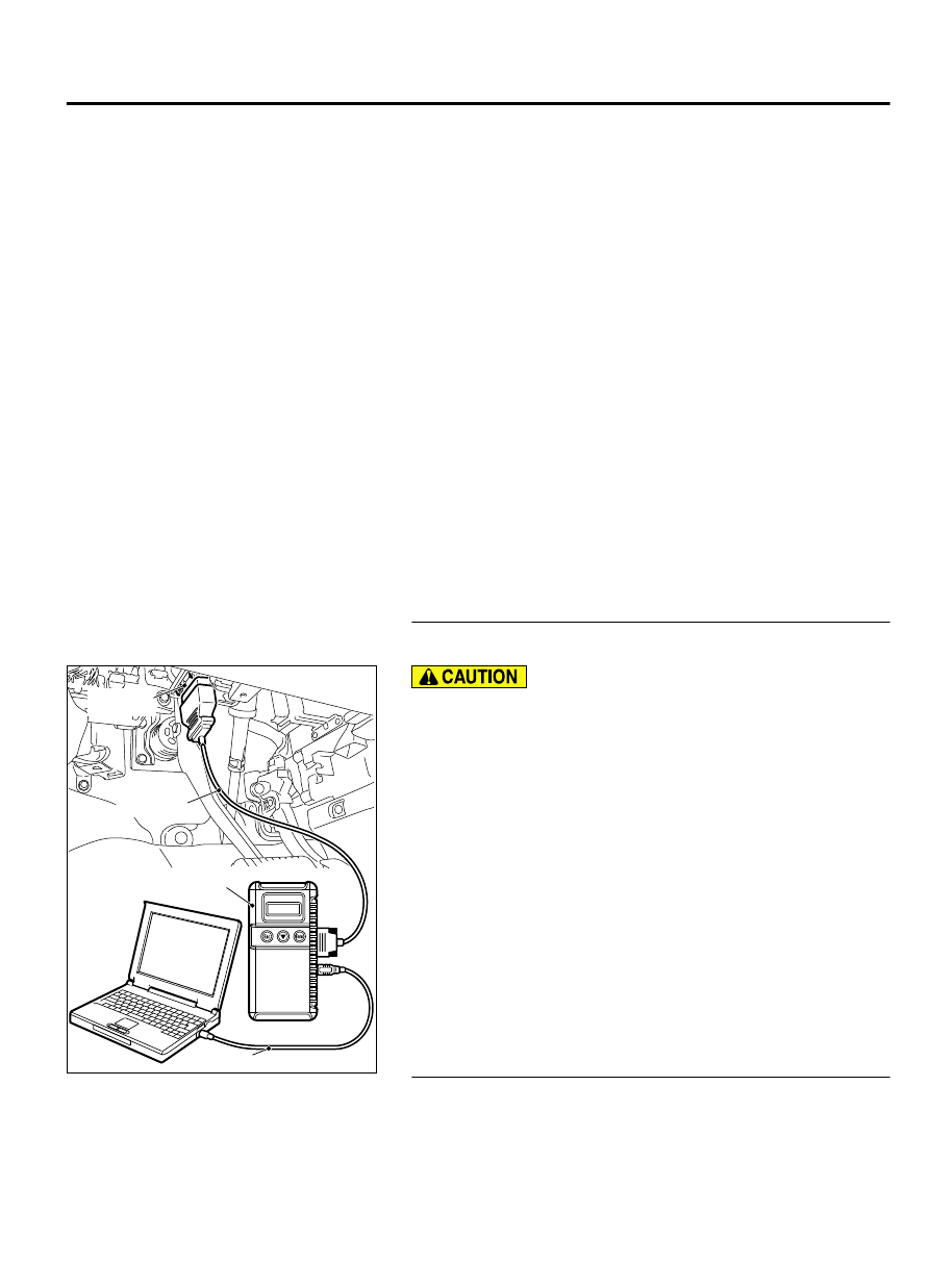
STEP 1. Using scan tool MB991958, diagnose the CAN bus
line
ZC501967
AC404789
ZC5019680000
MB991824
MB991827
MB991910
Data link
connector
To prevent damage to scan tool MB991958, always turn the
ignition switch to the "LOCK" (OFF) position before
connecting or disconnecting scan tool MB991958.
(1)
Connect scan tool MB991958. Refer to "How to connect the
Scan Tool (M.U.T.-III) P.55A-6."
(2)
Turn the ignition switch to the "ON" position.
(3)
Diagnose the CAN bus line.
(4)
Turn the ignition switch to the "LOCK" (OFF) position.
Q:Is the CAN bus line found to be normal?
YES:
Go to Step 2.
NO:
Repair the CAN bus line. (Refer to GROUP 54D,
STEP 2. Using scan tool MB991958 read the Occupant
classification-ECU diagnostic trouble code.
Check whether an Occupant classification-ECU DTCs are set or
not.
AIR CONDITIONING
55A-47
MANUAL A/C DIAGNOSIS