Content .. 1134 1135 1136 1137 ..
Mitsubishi Outlander XL. Manual - part 1136
(1)
Disconnect the scan tool and ETACS-ECU connector C-301,
and check the wiring harness.
(2)
Check the wiring harness between data link connector C-125
(terminal No.6) and ETACS-ECU connector C-301 (terminal
No.5) <CAN_H>
(3)
Check the wiring harness between data link connector C-125
(terminal No.14) and ETACS-ECU connector C-301
(terminal No.4) <CAN_L>
Q:Is the wiring harness between data link connector C-125
and ETACS-ECU connector C-301 in good condition?
YES:
Go to Step 3.
NO:
Repair the wiring harness between data link connector
C-125 and ETACS-ECU connector C-301.
STEP 3. Check the wiring harness between data link
connector C-125 and ETACS-ECU connector C-301 for a
short to ground. Measure the resistance at data link
connector C-125.
Disconnect the negative battery terminal. For details refer
to P.54D-8.
A digital multimeter should be used. For details refer to P.
54D-8.
The test wiring harness should be used. For details refer
to P.54D-8.
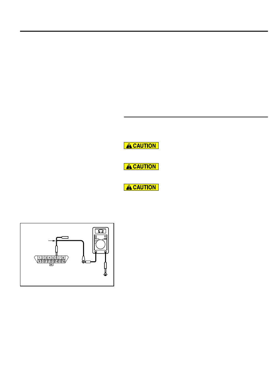
(1)
Disconnect the scan tool and ETACS-ECU connector C-301,
and measure the resistance at the wiring harness side of data
link connector C-125.
ZC5010410000
Harness side: C-125
Test harness
(2)
Measure the resistance between data link connector terminal
6 and body ground. <CAN_H>
OK: 1 kiloohm or more
CONTROLLER AREA NETWORK (CAN)
54D-27
DIAGNOSIS