Content .. 1064 1065 1066 1067 ..
Mitsubishi Outlander XL. Manual - part 1066
ZC501967
AC404789
ZC5019680000
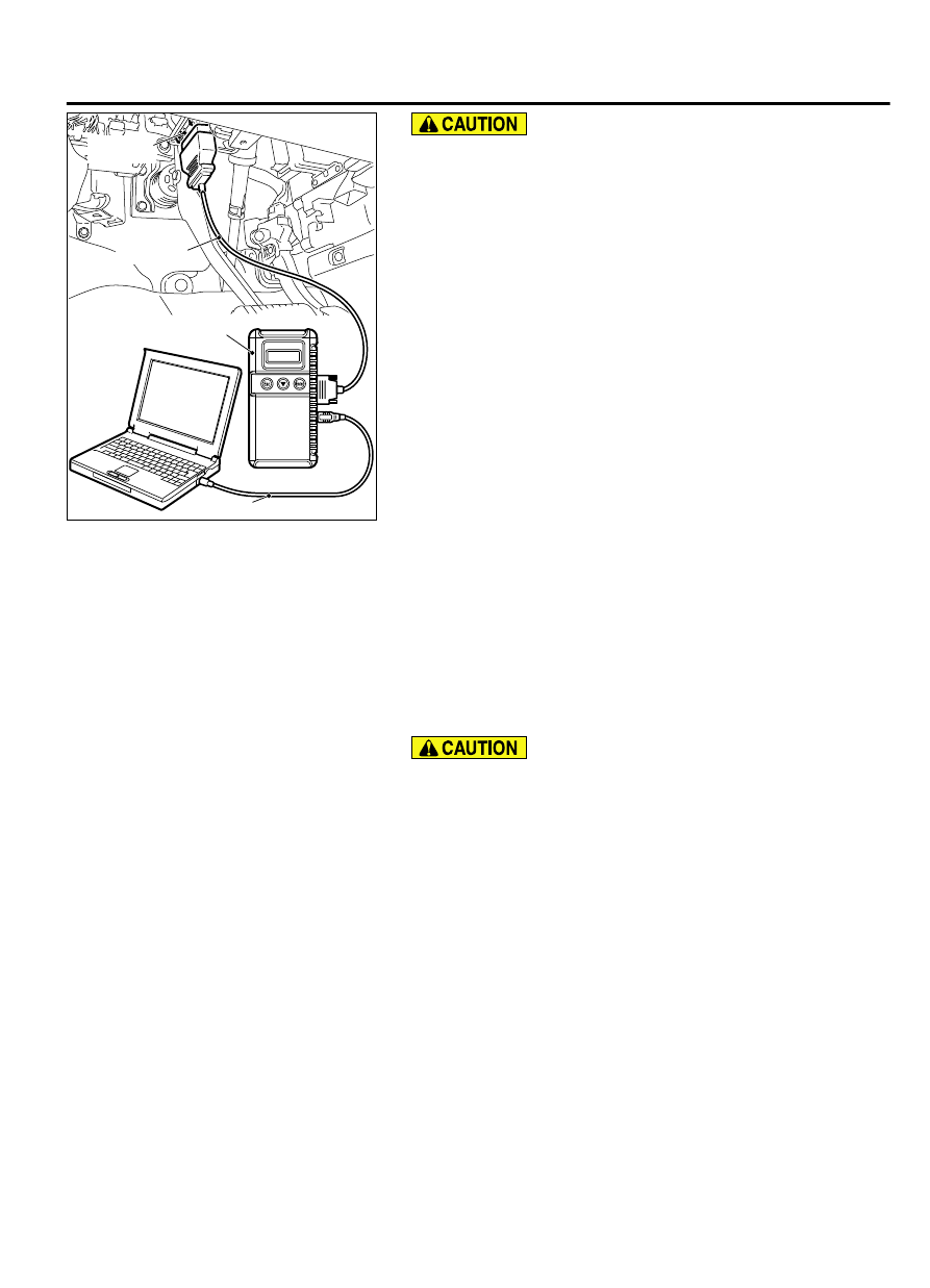
MB991824
MB991827
MB991910
Data link
connector
To prevent damage to scan tool MB991958, always turn the
ignition switch to the "LOCK" (OFF) position before
connecting or disconnecting scan tool MB991958.
1.
Ensure that the ignition switch is at the "LOCK" (OFF) position.
2.
Start up the personal computer.
3.
Connect special tool MB991827 to special tool MB991824 and
the personal computer.
4.
Connect special tool MB991910 to special tool MB991824.
5.
Connect special tool MB991910 to the data link connector.
6.
Turn the power switch of special tool MB991824 to the "ON"
position.
NOTE:
When special tool MB991824 is energized, special
tool MB991824 indicator light will be illuminated in a
green color.
7.
Start the M.U.T.-III system on the personal computer.
NOTE:
Disconnecting scan tool MB991958 is the reverse of
the connecting sequence, making sure that the ignition
switch is at the "LOCK" (OFF) position.
HOW TO READ AND ERASE DIAGNOSTIC
TROUBLE CODES
Required Special Tools:
⦆
MB991958: Scan Tool (M.U.T.-III Sub Assembly)
⦆
MB991824: Vehicle Communication Interface (V.C.I.)
⦆
MB991827: M.U.T.-III USB Cable
⦆
MB991910: M.U.T.-III Main Harness A (Vehicles with
CAN communication system)
To prevent damage to scan tool MB991958, always turn the
ignition switch to the "LOCK" (OFF) position before
connecting or disconnecting scan tool MB991958.
NOTE:
If the battery voltage is low, diagnostic trouble
codes will not be set. Check the battery if scan tool
MB991958 does not display.
1.
Connect scan tool MB991958 to the data link connector.
2.
Turn the ignition switch to the "ON" position.
3.
Select "System select" from the start-up screen.
4.
Select "From 2006 MY" of "Model Year." When the "Vehicle
Information" is displayed, check the contents.
5.
Select "ETACS" from "System List", and press the "OK"
button.
NOTE:
When the "Loading Option Setup" list is displayed,
check the applicable item.
6.
Select "Diagnostic Trouble Code."
7.
If a DTC is set, it is shown.
8.
Choose "Erase DTCs" to erase the DTC.
ALARM SYSTEM
54Af-5
DIAGNOSIS