Mitsubishi Outlander XL. Manual - part 1063


  Index      Mitsubishi     Mitsubishi Outlander XL - service repair manual 2007 year


Search            


Content   ..  1061  1062  1063  1064   ..


Mitsubishi Outlander XL. Manual - part 1063


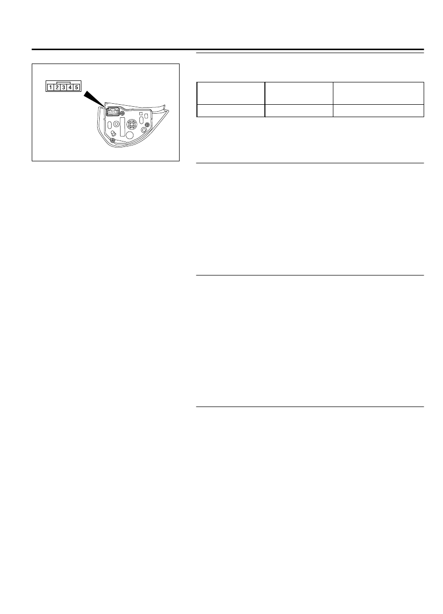
STEP 4. Check the steering audio switch.

ZC6016200000

Remove  the  steering  audio  switch.  Then  check  continuity
between the switch terminals.

Switch Position Tester

Connection

Measurement Value

No push

2 - 3

Approximately 3.1 kΩ

Q:Is the steering audio switch in good condition?

YES:

 Go to Step 5.

NO:

 Replace the steering audio switch.

STEP 5. Check steering voice-control switch connector
C-206 and steering audio switch connector C-213 for loose,
corroded or damaged terminals, or terminals pushed back
in the connector.

Q:Are  steering  voice-control  switch  connector  C-206  and

steering  audio  switch  connector  C-213  in  good

condition?

YES:

 Go to Step 6.

NO:

 Repair or replace the damaged component(s). Refer to

GROUP 00E, Harness Connector Inspection P.00E-2. The
steering remote control switch should work normally.

STEP 6. Check the wiring harness between steering voice-
control switch connector C-206 (terminal 3) and steering
audio switch connector C-213 (terminal 3).

Check  the  communication  lines  for  open  circuit  and  short
circuit.

Q:Is  the  wiring  harness  between  steering  voice-control

switch connector C-206 (terminal 3) and steering audio

switch connector C-213 (terminal 3) in good condition?

YES:

 Go to Step 7.

NO:

 The wiring harness may be damaged or the connector

(s) may have loose, corroded or damaged terminals, or
terminals pushed back in the connector. Repair the wiring
harness as necessary.

STEP 7. Check the wiring harness between steering voice-
control switch connector C-206 (terminal 2) and clock
spring connector C-202 (terminal 4).

Check  the  communication  lines  for  open  circuit  and  short
circuit.

Q:Is  the  wiring  harness  between  steering  voice-control

switch  connector  C-206  (terminal  2)  and  clock  spring

connector C-202 (terminal 4) in good condition?

YES:


Go to Step 8.

NO:

 The wiring harness may be damaged or the connector

(s) may have loose, corroded or damaged terminals, or
terminals pushed back in the connector. Repair the wiring
harness as necessary.

ACCESSORY

54Ae-31

HANDS-FREE CELLULAR PHONE SYSTEM

STEP 8. Retest the system
Check that the hands-free cellular phone system works normally
when the steering voice-control switch is operated.

Q:Check that the hands-free cellular phone system works

normally  when  the  steering  voice-control  switch  is

operated.

YES:

 The trouble can be an intermittent malfunction

(Refer to GROUP 00, How to use Troubleshooting/inspection
Service Points, How to Cope with Intermittent
Malfunction P.00-15).

NO:

 Replace the radio and CD changer <vehicles without

MMCS> or audio visual navigation unit <vehicles with
MMCS>.

Inspection Procedure 5: The cellular phone is not recognized or the connection cannot
be established.

M15410400023USA0000010000

FUNCTION
With  the  hands-free  cellular  phone  system,  the
cellular phone and hands-free module communicate
with each other by using Bluetooth™.

TROUBLE JUDGMENT CONDITIONS
When the cellular phone cannot be recognized or the
communication  cannot  be  established,  the  cellular
phone or hands-free module may be defective.

TROUBLESHOOTING HINTS

Malfunction of the cellular phone

Malfunction of the hands-free module

DIAGNOSIS

STEP 1. Check the cellular phone.
Check that the cellular phone can be used normally
as a unit.

Q:Is  it  possible  to  use  the  cellular  phone

normally?

YES:

 Go to Step 2.

NO:

 Repair or replace the cellular phone.

STEP 2. Check the position of cellular phone.
Check  that  the  function  becomes  normal  when  the
cellular  phone  is  moved  closer  to  the  hands-free
module.

Q:Does  the  function  become  normal  when  the

cellular  phone  is  moved  closer  to  the  hands-

free module?

YES:

 No action is necessary and testing is

complete.

NO:

 Go to Step 3.

STEP 3. Check the registration method of cellular
phone.
By referring to the operation manuals, check that the
cellular  phone  was  registered  to  the  hands-free
module by following the normal procedure.

Q:Was the cellular phone registered by following

the normal procedure?

YES:

 Check the trouble symptom, and finish when

it is normal. When the abnormality is present,
go to Step 4.

NO:

 Register a cellular phone according to a

regular procedure.

STEP 4. Temporarily replace the cellular phone,
and check the trouble symptom.
Temporarily  register  a  separate  Bluetooth™-
supported cellular phone, and check that the hands-
free cellular phone system operates normally.

Q:Is  the  normal  conversation  possible  with  the

hands-free system?

YES:

 Ask the customer to have the cellular

phone repaired or replaced. Then, delete the
temporarily registered cellular phone. Once the

54Ae-32

ACCESSORY

HANDS-FREE CELLULAR PHONE SYSTEM

customer prepares the normally-working cellular
phone, register the cellular phone to the hands-
free module.

NO:

 Replace the hands-free module.

Inspection Procedure 6: Check the hands-free module power supply circuit.

M15410400026USA0000010000

Hands Free Module Power Supply Circuit

FUSIBLE
LINK

36

HANDS FREE 
MODULE

RELAY BOX
 ENGINE 
 COMPARTMENT

ZC6008760005

Connector: C-121

ZC6008780002

Connector: C-307, C-317

C-307 (B)

C-317


CIRCUIT OPERATION

The  power  supply  to  the  hands-free  module  is
provided by the fusible link (36).

If  the  power  supply  system  from  the  battery  is
defective, the system operates by the power supply
from the ignition switch (IG1).

ACCESSORY

54Ae-33

HANDS-FREE CELLULAR PHONE SYSTEM

TECHNICAL DESCRIPTION (COMMENT)
If  the  hands-free  cellular  phone  system  don't  work,
power  supply  and  ground  system  to  the  hands-free
module,  or  the  hands-free  module  itself  may  be
defective.

TROUBLESHOOTING HINTS

The wiring harness or connectors may have loose,
corroded,  or  damaged  terminals,  or  terminals
pushed back in the connector

The hands-free module may be defective

DIAGNOSIS

Required Special Tools:

MB991223: Harness Set

MB992006: Extra Fine Probe

STEP 1. Check hands-free module connector C-121 for
loose, corroded or damaged terminals, or terminals pushed
back in the connector.

Q:Is  hands-free  module  connector  C-121  in  good

condition?

YES:

 Go to Step 2.

NO:

 Repair or replace the damaged component(s). Refer to

GROUP 00E, Harness Connector Inspection P.00E-2.

STEP 2. Check the ground circuit to the hands-free module.
Measure the resistance at hands-free module connector
C-121.

(1)

Disconnect  hands-free  module  connector  C-121,  and
measure at the wiring harness side.

ZC5010410045

Harness side: C-121

(2)

Measure  the  resistance  value  between  terminal  15  and
ground.

OK: The resistance should be 2 ohms or less.

Q:Is the measured resistance 2 ohms or less?

YES:

 Go to Step 4.

NO:

 Go to Step 3.

STEP 3. Check the wiring harness between hands-free
module connector C-121 (terminal 15) and ground.

Q:Is  the  wiring  harness  between  hands-free  module

connector  C-121  (terminal  15)  and  ground  in  good

condition?

YES:

 Replace the hands-free module. The system should

communicate with the hands-free module normally.

NO:

 The wiring harness may be damaged or the connector

(s) may have loose, corroded or damaged terminals, or
terminals pushed back in the connector. Repair the wiring
harness as necessary.

STEP 4. Check the wiring harness between hands-free
module connector C-121 (terminal 15) and fusible link (36).

NOTE: 

Also check ETACS-ECU connectors C-307 and C-317 for

loose, corroded, or damaged terminals, or terminals pushed

54Ae-34

ACCESSORY

HANDS-FREE CELLULAR PHONE SYSTEM


Content   ..  1061  1062  1063  1064   ..