Content .. 1058 1059 1060 1061 ..
Mitsubishi Outlander XL. Manual - part 1060
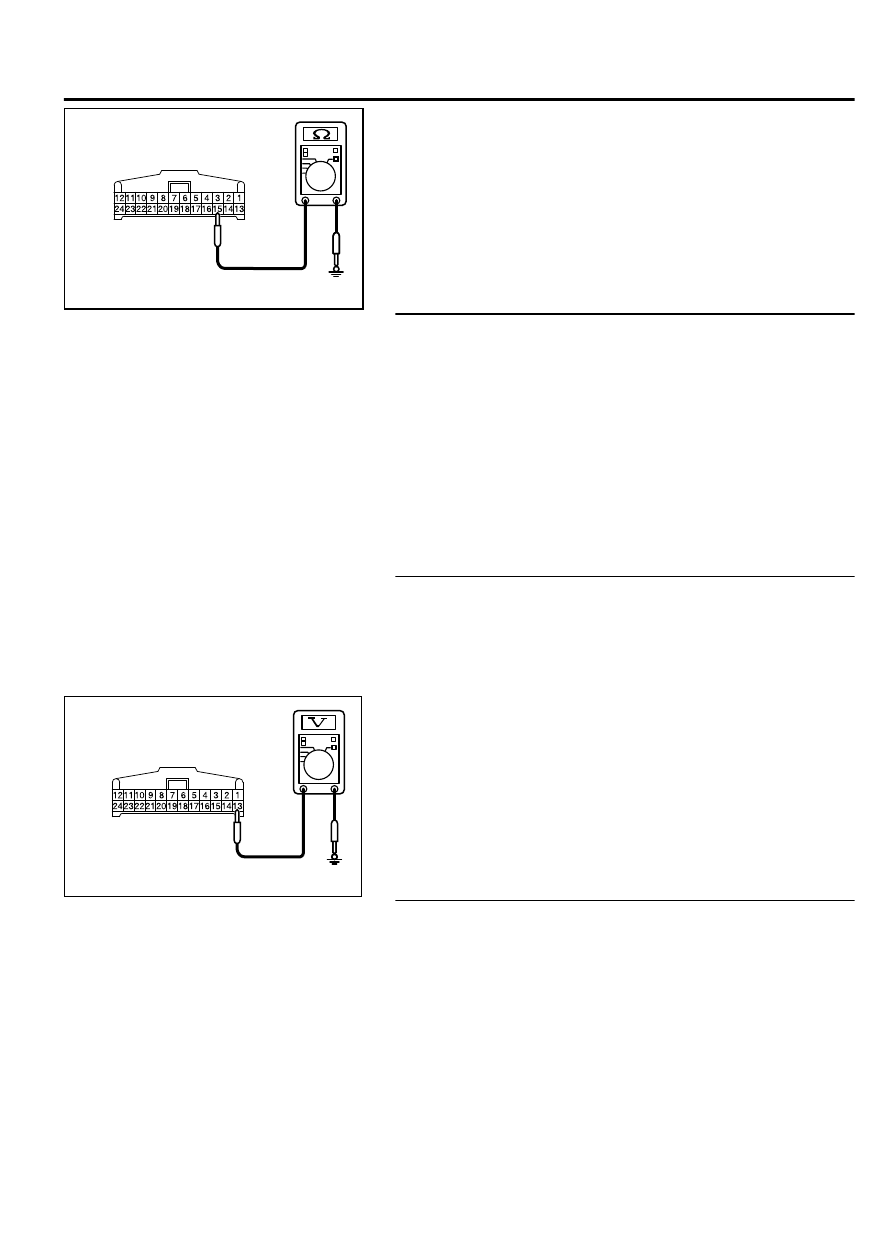
ZC5010410045
Harness side: C-121
(2)
Measure resistance between terminal 15 and ground.
OK: The resistance should be 2 ohm or less.
Q:Is the measured resistance 2 ohms or less?
YES:
Go to Step 7.
NO:
Go to Step 6.
STEP 6. Check the wiring harness between hands-free
module connector C-121 (terminal 15) and ground.
Q:Is the wiring harness between hands-free module
connector C-121 (terminal 15) and ground in good
condition?
YES:
The trouble can be an intermittent malfunction
(Refer to GROUP 00, How to use Troubleshooting/inspection
Service Points, How to Cope with Intermittent
Malfunction P.00-15).
NO:
The wiring harness may be damaged or the connector
(s) may have loose, corroded or damaged terminals, or
terminals pushed back in the connector. Repair the wiring
harness as necessary.
STEP 7. Check the power supply circuit to the hands-free
module. Measure the voltage at hands-free module
connector C-121.
(1)
Disconnect hands-free module connector C-121, and
measure the voltage available at the hands-free module side
of the connector.
ZC5010400049
Harness side: C-121
(2)
Measure the voltage between terminal 13 and ground.
OK: The voltage should measure approximately 12
volts (battery positive voltage).
Q:Is the measured voltage approximately 12 volts (battery
positive voltage)?
YES:
Go to Step 9.
NO:
Go to Step 8.
STEP 8. Check the wiring harness between hands-free
module connector C-121 (terminal 13) and ETACS-ECU
connector C-317 (terminal 1).
Q:Is the wiring harness between hands-free module
connector C-121 (terminal 13) and ETACS-ECU
connector C-317 (terminal 1) in good condition?
YES:
The trouble can be an intermittent malfunction
(Refer to GROUP 00, How to use Troubleshooting/inspection
Service Points, How to Cope with Intermittent
Malfunction P.00-15).
ACCESSORY
54Ae-19
HANDS-FREE CELLULAR PHONE SYSTEM