Content .. 1010 1011 1012 1013 ..
Mitsubishi Outlander XL. Manual - part 1012
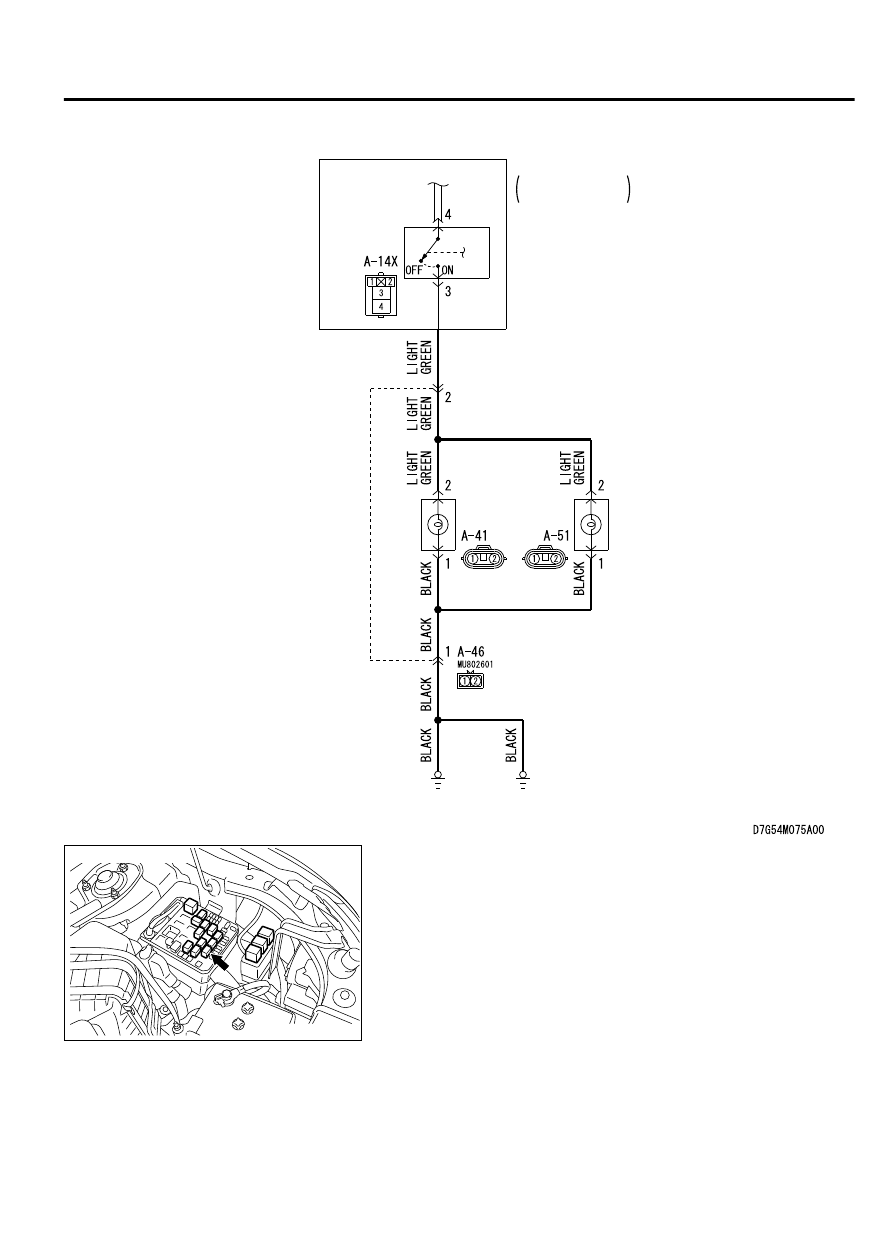
FOG LIGHT
RELAY
RELAY BOX
ENGINE
COMPARTMENT
FOG LIGHT
(LH) (RH)
Fog Light Circuit
ZC6041270002
Connector: A-14X
LIGHTING
54Ac-121
DIAGNOSIS
|
|
|
Content .. 1010 1011 1012 1013 ..
FOG LIGHT RELAY BOX ENGINE FOG LIGHT Fog Light Circuit ZC6041270002 Connector: A-14X LIGHTING 54Ac-121 DIAGNOSIS |