Mitsubishi Outlander GS45X. Manual - part 981
 

  Index      Mitsubishi     Mitsubishi Outlander GS45X - service repair manual


Search            


Content   ..  979  980  981  982   ..


Mitsubishi Outlander GS45X. Manual - part 981


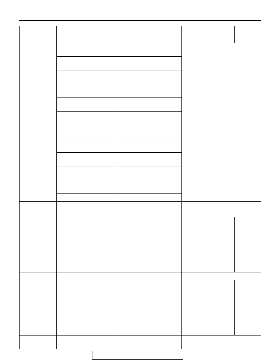
MULTIPORT FUEL INJECTION (MFI) DIAGNOSIS

TSB Revision

MULTIPORT FUEL INJECTION (MFI) <3.0L ENGINE>

13B-857

41

Oxygen sensor heater 
monitoring

HTR_ENA: YES

EGR and/or VVT system 
monitoring

EGR_ENA: YES

Completion status of 
non-continuous monitors 
this monitoring cycle:

Completion status of 
non-continuous monitors 
this monitoring cycle:

Catalyst monitoring 
completed

CAT_CMPL: YES or NO

Heated catalyst 
monitoring completed

HCATCMPL: YES

Evaporative system 
monitoring completed

EVAPCMPL: YES or NO

Secondary air system 
monitoring completed

AIR_CMPL: YES

Oxygen sensor 
monitoring completed

O2S_CMPL: YES or NO

Oxygen sensor heater 
monitoring completed

HTR_CMPL: YES or NO

EGR and/or VVT system 
monitoring completed

EGR_CMPL: YES or NO

42

Control module voltage

VPWR: xx.xx V

See M.U.T.-III item No. 1.

43

Absolute Load Value

LOAD_ABS: xxxxx.x %

See M.U.T.-III item No. 72.

44

Fuel/Air Commanded 
Equivalence Ratio

LAMBDA: xxx.xxx

Engine: running

• "1" means 

"stoichiometric 
air fuel ratio". 
The smaller air 
fuel ratio, the rich 
return. The more 
air fuel ratio, the 
lean return.

− 1.999

(Display 
range)

45

Relative Throttle Position TP_R: xxx.x%

See M.U.T.-III item No. BC.

46

Ambient air temperature

AAT: xxx

°C (xxx°F)

• Ignition 

switch: 
"ON"

• Engine is 

cold state

The value 
displayed 
approxima
tely 
matches 
the 
ambient 
temperatu
re

47

Absolute Throttle Position 
B

TP_B: xxx.x%

See M.U.T.-III item No. BD.

PARAMETER 
IDENTIFICATION 
(PID)

DESCRIPTION

COMMON EXAMPLE OF 
GENERAL SCAN TOOL 
DISPLAY

INSPECTION 
CONDITION

NORMAL 
CONDITION

MULTIPORT FUEL INJECTION (MFI) DIAGNOSIS

TSB Revision

MULTIPORT FUEL INJECTION (MFI) <3.0L ENGINE>

13B-858

ACTUATOR TEST REFERENCE TABLE

M1131152503074

NOTE: : Continues for 27 minutes. Can be released 
by pressing the CLEAR key.

49

Accelerator Pedal 
Position D

APP_D: xxx.x%

See M.U.T.-III item No. BE.

4A

Accelerator Pedal 
Position E

APP_E: xxx.x%

See M.U.T.-III item No. BF.

4C

Commanded Throttle 
Actuator Control

TAC_PCT: xxx.x%

See M.U.T.-III item No. 58.

5A

Relative Accelerator 
Pedal Position

APP_R: xxx.x%

See M.U.T.-III item No. DD.

PARAMETER 
IDENTIFICATION 
(PID)

DESCRIPTION

COMMON EXAMPLE OF 
GENERAL SCAN TOOL 
DISPLAY

INSPECTION 
CONDITION

NORMAL 
CONDITION

M.U.T.-III 
SCAN TOOL 
DISPLAY

ITEM 
NO.

INSPECTION ITEM DRIVE 

CONTENTS

INSPECTION 
REQUIRMENT

NORMAL 
CONDITION

INSPECTION 
PROCEDURE 
NO.

REFERECE 
PAGE

A/C relay

16

A/C compressor 
clutch relay

A/C 
compresso
r clutch 
relay turns 
from OFF 
to ON.

Ignition switch: 
"ON"

Clicks when 
A/C 
compressor 
clutch is 
driven.

Procedure 
No. 25

P.13B-829

Cooling fan 14

Radiator fan, 
A/C condenser 
fan

Drive the 
fan motor.

Ignition switch: 
"ON"

Radiator 
fan and A/C 
condenser 
fan rotate.

EVAP. 
emission 
purge SOL. 
Valve

10

Evaporative 
emission purge 
solenoid

Solenoid 
valve turns 
from OFF 
to ON.

Ignition switch: 
"ON"

Clicks when 
solenoid 
valve is 
driven.

Code No. 
P0443

P.13B-483

EVAP. 
emission 
ventilation 
SOL.

15

Evaporative 
emission 
ventilation 
solenoid

Solenoid 
valve turns 
from OFF 
to ON.

Ignition switch: 
"ON"

Clicks when 
solenoid 
valve is 
driven.

Code No. 
P0446

P.13B-490

Fuel pump

9

Fuel pump

Fuel pump 
operates 
and fuel is 
recirculate
d.

• Ignition 

switch: "ON"

• Listen near 

the fuel tank 
for the sound 
of fuel pump 
operation.

Sound of 
operation is 
heard.

Procedure 
No. 22

P.13B-810

MULTIPORT FUEL INJECTION (MFI) DIAGNOSIS

TSB Revision

MULTIPORT FUEL INJECTION (MFI) <3.0L ENGINE>

13B-859

Ignition 
timing 5 
BTDC

11*

Basic ignition 
timing

Set to 
ignition 
timing 
adjustment 
mode.

• Engine: idling

• Connect 

timing light

5

°BTDC

Injector stop 1

Injectors

Specified 
injector is 
stopped.

Engine: warm 
up, idle (cut the 
fuel supply to 
each injector in 
turn and check 
cylinders which 
don't affect 
idling.)

Idle 
condition is 
changed by 
stopping 
selected 
cylinder: 
this can 
cause an 
unstable 
condition 
and the 
engine may 
stall.

Code No. 
P0201, 
P0202, 
P0203, 
P0204, 
P0205, 
P0206

P.13B-345

P.13B-353

P.13B-360

P.13B-368

P.13B-375

P.13B-383

Oil control 
valve

17

Engine oil 
control valve

Switch the 
engine oil 
control 
valve from 
OFF to 
ON.

Engine: warm 
up, idle

When the 
valve is 
actuated, 
operating 
noise is 
audible.

Code No. 
P001A

P.13B-58

M.U.T.-III 
SCAN TOOL 
DISPLAY

ITEM 
NO.

INSPECTION ITEM DRIVE 

CONTENTS

INSPECTION 
REQUIRMENT

NORMAL 
CONDITION

INSPECTION 
PROCEDURE 
NO.

REFERECE 
PAGE

MULTIPORT FUEL INJECTION (MFI) DIAGNOSIS

TSB Revision

MULTIPORT FUEL INJECTION (MFI) <3.0L ENGINE>

13B-860

CHECK AT THE ENGINE CONTROL MODULE (ECM)

M1131153502104

1. Disconnect the ECM connectors B-10 and B-11, 

and connect check harness special tool 
MB992110 between the ECM connectors.

2. Measure the voltage between each check 

harness connector terminal and check harness 
connector ground terminal (No. 25 or No. 29).

TERMINAL VOLTAGE CHECK CHART

NOTE: *

1

: The average voltage through an analog 

voltmeter is described in this service manual 
(because the average voltage would be not con-
stantly shown on a digital voltmeter).

NOTE: *

2

: Vehicles for Canada, the headlight, tail-

light, etc. remain lit even when the lighting switch is 
in "OFF" position but is no problem for checks.

AK700419

82 81 80 79 78 77 76 75 74 73 72 71

94 93 92 91 90 89 88 87 86 85 84 83

99 98 97 96 95

100

101

102

103

104

105

106

112

113

114

109 108

107

110

111

115

116

117

118

16 15 14 13 12 11 10 9 8 7 6 5 4 3

2

1

32 31 30 29 28 27 26 25 24 23 22 21 20 19 18 17

48 47 46 45 44 43 42 41 40 39 38 37 36 35 34 33

64 63 62 61 60 59 58 57 56 55 54 53 52 51 50 49

AB

B-10

B-11

Check Harness Special Tool MB992110 Connector Terminal Arrangement

TERMINAL 
NO.

INSPECTION ITEM INSPECTION CONDITION (ENGINE 

CONDITION)

NORMAL 
CONDITION

1

Engine oil control 
valve

Engine: warming up, idling

B+

Engine: 5,000 r/min

1 V or less 

→ 4.0 − 

10 V*

1

 (After a few 

seconds pass)

2

No. 1 injector

• Engine: warming up, idling

• Suddenly depress the accelerator pedal

From 9 

− 14 V*

1


momentarily drops 
slightly

3

No. 2 injector

18

No. 3 injector

19

No. 4 injector

50

No. 5 injector

51

No. 6 injector


Content   ..  979  980  981  982   ..