Mitsubishi Outlander GS45X. Manual - part 974


  Index      Mitsubishi     Mitsubishi Outlander GS45X - service repair manual


Search            


Content   ..  972  973  974  975   ..


Mitsubishi Outlander GS45X. Manual - part 974


MULTIPORT FUEL INJECTION (MFI) DIAGNOSIS

TSB Revision

MULTIPORT FUEL INJECTION (MFI) <3.0L ENGINE>

13B-829

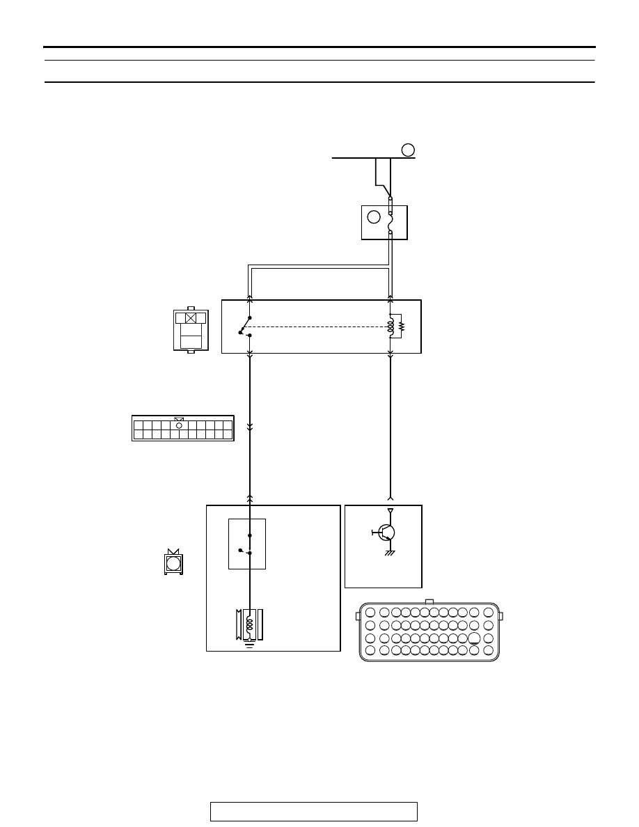
INSPECTION PROCEDURE 25: A/C system.

AK900376

71 72 73 74 75 76 77 78 79 80 81 82

83 84 85 86 87 88 89 90 91 92 93 94

95 96 97 98 99

100 101 102 103 104

112 113 114

109

108

107

110 111

115 116

106

105

118

117

1

2

3
4

1

10 111213 14 1516 17 1819 20

2 3 4

5 6 7 8 9


1

WHITE

WHITE

7

10A

ORANGE

A/C COMPRESSOR
CLUTCH RELAY

4

2

1

A-16X

B-17

MU802655

A-13

OFF

A/C
REFRIGERANT
TEMPERATURE
SWITCH 

A/C COMPRESSOR CLUTCH ASSEMBLY

A/C
COMPRESSOR
CLUTCH

A/C COMPRESSOR CLUTCH RELAY CIRCUIT

102

AC

B-11

LIGHT GREEN

LIGHT GREEN

3

1

5

OFF

ON

ON

FUSIBLE LINK  36

ON

OFF

: 155˚C
OFF

ON

: 125˚C

RELAY BOX
(ENGINE COMPARTMENT)

ENGINE CONTROL MODULE

MULTIPORT FUEL INJECTION (MFI) DIAGNOSIS

TSB Revision

MULTIPORT FUEL INJECTION (MFI) <3.0L ENGINE>

13B-830

.

CIRCUIT OPERATION

• When the A/C switch ON signal is input into the 

ECM, the ECM turns ON the A/C compressor 
relay. This causes battery positive voltage to be 
supplied to the A/C compressor and the magnet 
latch actuates.

.

COMMENT

• When the A/C is "ON" the ECM turns "ON" the 

power transistor in the ECM. The ECM delays 
A/C engagement momentarily while it increases 
idle r/min. Then the A/C compressor clutch relay 
coil will be energized. 

With this, the A/C compressor clutch relay turns 
"ON", and the A/C compressor clutch operates.

.

TROUBLESHOOTING HINTS (The most 
likely causes for this case: )

• Malfunction of the A/C control system.

• Improper connector contact, open circuit or 

short-circuited harness wire.

• Malfunction of the ECM.

AK700402AB

ECM

B-11 (GR)

Connector: B-11

AK900602

Connector: A-13

A-13

AB

AK900156 AD

Connector: B-17

B-17 (B)

AK700440AB

A/C compressor relay

A-16X

Connector: A-16X

MULTIPORT FUEL INJECTION (MFI) DIAGNOSIS

TSB Revision

MULTIPORT FUEL INJECTION (MFI) <3.0L ENGINE>

13B-831

DIAGNOSIS

STEP 1. Using scan tool MB991958, check data list item.

CAUTION

To prevent damage to scan tool MB991958, always turn the 
ignition switch to the "LOCK" (OFF) position before con-
necting or disconnecting scan tool MB991958.
(1) Connect scan tool MB991958 to the data link connector.
(2) Turn the ignition switch to the "ON" position.
(3) Check the following items in the data List.

Refer to Data List Reference Table 

P.13B-836

.

a. Item 93: A/C compressor relay.

(4) Turn the ignition switch to the "LOCK" (OFF) position.
Q: Are they operating properly?

YES : Go to Step 2.
NO :  Repair or replace it. Then confirm that the malfunction 

symptom is eliminated.

STEP 2. Check the circuit at ECM connector B-11.
(1) Disconnect the connectors B-11 and measure at the 

harness side.

(2) Turn the ignition switch to the "ON" position.
(3) Measure the voltage between terminal No. 102 and ground.

• Voltage should be battery positive voltage.

(4) Using a jumper wire, connect terminal No. 102 to ground.

• A/C compressor clutch relay should turn "ON".

(5) Turn the ignition switch to the "LOCK" (OFF) position.
Q: Is the voltage and A/C compressor relay condition 

normal?
YES : 
Replace the ECM. When the ECM is replaced, 

register the ID code. Refer to GROUP 42B, Diagnosis 
− ID Codes Registration Judgment Table <Vehicles 

with KOS> 

P.42B-15

 or GROUP 42C, Diagnosis 

− ID 

Codes Registration Judgment Table <Vehicles with 
WCM> 

P.42C-10

.

NO  :  Refer to GROUP 55A, Manual A/C Diagnosis 

− 

Heater, Air Conditioning and Ventilation Diagnostic 
Troubleshooting Strategy 

P.55A-6

, or GROUP 55B, 

Auto A/C Diagnosis 

− Automatic A/C Troubleshooting 

Strategy 

P.55B-4

.

AK700568AB

MB991824

MB991827

MB991910

Data link
connector

82 81 80 79 78 77 76 75 74 73 72 71

94 93 92 91 90 89 88 87 86 85 84 83

99 98 97 96 95

100

101

102

103

104

105

106

112

113

114

109 108

107

110

111

115

116

117

118

AK700226AB

B-11 harness
connector:
component side 

MULTIPORT FUEL INJECTION (MFI) DIAGNOSIS

TSB Revision

MULTIPORT FUEL INJECTION (MFI) <3.0L ENGINE>

13B-832

INSPECTION PROCEDURE 26: Engine oil pressure switch (for warning lamp) System

.

CIRCUIT OPERATION

• Battery voltage is applied to the oil pressure 

switch (terminal No. 1) from the engine-ECU (ter-
minal No. 36).

.

COMMENT

• Detect the engine oil pressure conditions and 

enter the result into the ECM. After starting the 
engine if the oil pressure rises to higher than the 
given pressure, the engine oil pressure switch 
turns OFF. Under this condition the ECM sends 
the command of turning off the oil warning lamp 
to the combination meter via CAN.

.

TROUBLESHOOTING HINTS (The most 
likely causes for this code to be set are:)

• Engine oil pressure switch failed.

• Improper connector contact, open circuit or 

short-circuit harness wire.

• ECM failed.

DIAGNOSIS

Required Special Tools:

• MB991958: Scan Tool (M.U.T.-III Sub Assembly)

• MB991824: V.C.I.

• MB991827: USB Cable

• MB991910: Main Harness A

AK703911

1

2

3 4 5 6 7 8 9 10 11 12 13 14 15 16

17 18 19 20 21 22 23 24 25 26 27 28 29 30 31 32

33 34 35 36 37 38 39 40 41 42 43 44 45 46 47 48

49 50 51 52 53 54 55 56 57 58 59 60 61 62 63 64

1

ENGINE OIL PRESSURE SWITCH (FOR WARNING LAMP) CIRCUIT

36

GRA

Y

ENGINE OIL
PRESSURE SWITCH
(FOR WARNING LAMP)

B-16

1

AB

B-10

OFF

ON

ENGINE
CONTROL
MODULE

AK700442AB

Connector: B-16

B-16

Engine oil
pressure switch

AK700401AB

ECM

B-10 (GR)

Connector: B-10


Content   ..  972  973  974  975   ..