Mitsubishi Outlander GS45X. Manual - part 959


  Index      Mitsubishi     Mitsubishi Outlander GS45X - service repair manual


Search            


Content   ..  957  958  959  960   ..


Mitsubishi Outlander GS45X. Manual - part 959


MULTIPORT FUEL INJECTION (MFI) DIAGNOSIS

TSB Revision

MULTIPORT FUEL INJECTION (MFI) <3.0L ENGINE>

13B-769

STEP 4. Using scan tool MB991958, check actuator test.
(1) Turn the ignition switch to the "ON" position.
(2) Check the following items in the actuator test. Refer to 

Actuator Test Reference Tabl

P.13B-858

.

a. Item 9: Fuel Pump.

(3) Turn the ignition switch to the "LOCK" (OFF) position.
Q: Is the actuator operating properly?

YES : Go to Step 5.
NO :  Repair or Replace. Then confirm that the malfunction 

symptom is eliminated.

STEP 5. Check the ignition timing.
(1) Check the ignition timing at cranking.

Standard value: 5

° BTDC ± 3°

Q: Is the ignition timing normal?

YES : Go to Step 6.
NO :  Check for installed conditions of the timing belt. Then 

confirm that the malfunction symptom is eliminated.

STEP 6. Check the fuel pressure.
Refer to On-vehicle Service 

− Fuel Pressure Test 

P.13B-883

.

Q: Is the fuel pressure normal?

YES : Go to Step 7.
NO :  Check the following items, and repair or replace the 

defective items.

• Insufficient fuel pump discharge.

• Fuel pump filter clogged.

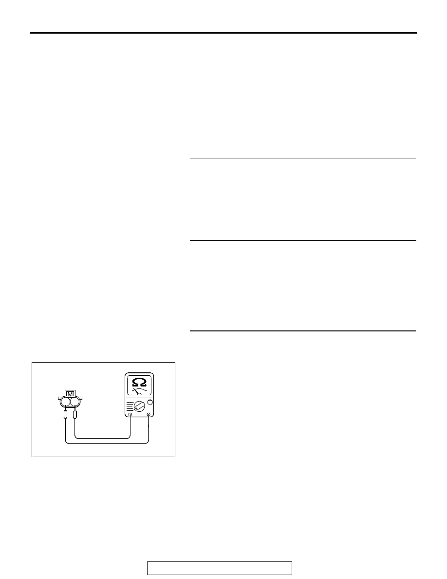
STEP 7. Check the left bank injector resistance.
(1) Disconnect the left bank injector connector B-115, B-116, 

B-120.

(2) Measure the resistance between each injector side 

connector terminal No. 1 and No. 2.

Standard value: 10.5 

 13.5 Ω [at 20°C (68°F)]

Q: Is the measured resistance between 10.5 and 13.5 ohms 

[at 20

°C (68°F)]?

YES : Go to Step 8.
NO :  Replace the faulty injector. Then confirm that the 

malfunction symptom is eliminated.

AK700204

1 2

AB

Injector side
connector

MULTIPORT FUEL INJECTION (MFI) DIAGNOSIS

TSB Revision

MULTIPORT FUEL INJECTION (MFI) <3.0L ENGINE>

13B-770

STEP 8. Check the right bank injector resistance at 
intermediate connector B-21.
(1) Disconnect the intermediate connector B-21.
(2) Measure the resistance between each male connector side 

terminal.

a. Measure the resistance between terminal No. 6 and No. 

7 at No. 1 cylinder injector.

b. Measure the resistance between terminal No. 6 and No. 

8 at No. 3 cylinder injector.

c. Measure the resistance between terminal No. 6 and No. 

9 at No. 5 cylinder injector.

• Resistance should be between 10.5 and 13.5 ohms [at 

20

°C (68°F)].

Q: Is the measured resistance between 10.5 and 13.5 ohms 

[at 20

°C (68°F)]?

YES : Go to Step 11.
NO :  Go to Step 9.

STEP 9. Check the right bank injector resistance.
(1) Remove the intake manifold.
(2) Disconnect the right bank injector connector, which 

deviates from the standard value at Step 8.

(3) Measure the resistance between injector side connector 

terminal No. 1 and No. 2.

Standard value: 10.5 

 13.5 Ω [at 20°C (68°F)]

Q: Is the measured resistance between 10.5 and 13.5 ohms 

[at 20

°C (68°F)]?

YES : Go to Step 10.
NO :  Replace the injector. Then confirm that the 

malfunction symptom is eliminated.

STEP 10. Check harness connector B-101, B-103, B-104 at 
right bank injector for damage.
(1) Check the injector connector, which deviated from the 

standard value listed in Step 8.

Q: Is the harness connector in good condition?

YES : Repair harness wire between injector intermediate 

connector and right bank injector connector because 
of harness damage. Then confirm that the 
malfunction symptom is eliminated.

NO :  Repair or replace it. Refer to GROUP 00E, Harness 

Connector Inspection 

P.00E-2

. Then confirm that the 

malfunction symptom is eliminated.

AK700205

1

2 3

6

7 8

4 5

9 10

AB

B-21
Injector side
connector

AK700204

1 2

AB

Injector side
connector

MULTIPORT FUEL INJECTION (MFI) DIAGNOSIS

TSB Revision

MULTIPORT FUEL INJECTION (MFI) <3.0L ENGINE>

13B-771

STEP 11. Check harness connector B-21 at the 
intermediate connector for damage.
Q: Is the harness connector in good condition?

YES : Go to Step 12.
NO :  Repair or replace it. Refer to GROUP 00E, Harness 

Connector Inspection 

P.00E-2

. Then confirm that the 

malfunction symptom is eliminated.

STEP 12. Check harness connector B-10 at ECM and 
harness connector B-115, B-116, B-120 at the left bank 
injector for damage.
Q: Is the harness connector in good condition?

YES : Go to Step 13.
NO :  Repair or replace it. Refer to GROUP 00E, Harness 

Connector Inspection 

P.00E-2

. Then confirm that the 

malfunction symptom is eliminated.

STEP 13. Check for harness damage between injector 
connector and ECM connector.
(1) Disconnect the injector connector and ECM connector.
(2) Measure the resistance between injector connector and 

ECM connector.

a. Injector connector B-101 (terminal No. 2) and ECM con-

nector B-10 (terminal No. 2) at No. 1 cylinder injector.

b. Injector connector B-120 (terminal No. 2) and ECM con-

nector B-10 (terminal No. 3) at No. 2 cylinder injector.

c. Injector connector B-103 (terminal No. 2) and ECM con-

nector B-10 (terminal No. 18) at No. 3 cylinder injector.

d. Injector connector B-116 (terminal No. 2) and ECM con-

nector B-10 (terminal No. 19) at No. 4 cylinder injector.

e. Injector connector B-104 (terminal No. 2) and ECM con-

nector B-10 (terminal No. 50) at No. 5 cylinder injector.

f. Injector connector B-115 (terminal No. 2) and ECM con-

nector B-10 (terminal No. 51) at No. 6 cylinder injector.

Q: Is the measured resistance less than 2 ohms?

YES : Go to Step 14.
NO :  Repair it. Then confirm that the malfunction symptom 

is eliminated.

AK700206

M

1

2

16 15 14 13 12 11 10 9 8 7 6 5 4 3

2

1

32 31 30 29 28 27 26 25 24 23 22 21 20 19 18 17

48 47 46 45 44 43 42 41 40 39 38 37 36 35 34 33

64 63 62 61 60 59 58 57 56 55 54 53 52 51 50 49

B-101, B-103, B-104,
B-115, B-116,B-120
harness connector:
component side 

AB

B-10 harness
connector:
component side 

MULTIPORT FUEL INJECTION (MFI) DIAGNOSIS

TSB Revision

MULTIPORT FUEL INJECTION (MFI) <3.0L ENGINE>

13B-772

STEP 14. Check the ignition system.
(1) Connect the timing light to terminal No. 3 of the ignition coil 

connector B-01, B-04, B-05, B-15, B-18 or B-19 in order.

(2) Crank the engine.

• The timing light flashes.

(3) Turn the ignition switch to the "LOCK" (OFF) position.
Q: Does the timing light flash?

YES : Go to Step 15.
NO :  Refer to INSPECTION PROCEDURE 24 

− Ignition 

Circuit System 

P.13B-823

.

STEP 15. Check the spark plugs.
Refer to GROUP 16, Ignition System 

− On-vehicle Service − 

Spark Plug Check And Cleaning 

P.16-45

.

Q: Are there any abnormalities?

YES : Replace the spark plug. Then confirm that the 

malfunction symptom is eliminated.

NO :  Go to Step 16.

STEP 16. Check the ignition coil.
(1) Remove the intake manifold.
(2) Refer to GROUP 16, Ignition System 

− On-vehicle Service 

− Ignition Coil Check 

P.16-44

.

Q: Are there any abnormalities?

YES : Replace the ignition coil. Then confirm that the 

malfunction symptom is eliminated.

NO :  Go to Step 17.

STEP 17. Check the compression pressure.
Refer to GROUP 11C, On-vehicle Service 

− Compression 

Pressure Check 

P.11C-18

.

Q: Is the compression pressure normal?

YES : Check the following items, and repair or replace the 

defective items.

a. Check if fuel is contaminated.
b. Check if the injectors are clogged.

Then confirm that the malfunction symptom is 

eliminated.

NO :  Repair it. Then confirm that the malfunction symptom 

is eliminated.


Content   ..  957  958  959  960   ..