Mitsubishi Outlander GS45X. Manual - part 936


  Index      Mitsubishi     Mitsubishi Outlander GS45X - service repair manual


Search            


Content   ..  934  935  936  937   ..


Mitsubishi Outlander GS45X. Manual - part 936


MULTIPORT FUEL INJECTION (MFI) DIAGNOSIS

TSB Revision

MULTIPORT FUEL INJECTION (MFI) <3.0L ENGINE>

13B-677

DIAGNOSIS

Required Special Tools:

• MB991958: Scan Tool (M.U.T.-III Sub Assembly)

• MB991824: V.C.I.

• MB991827: USB Cable

• MB991910: Main Harness A

STEP 1. Check harness connector C-123 at accelerator 
pedal position sensor and harness connector B-11 at ECM 
for damage.
Q: Is the harness connector in good condition?

YES : Go to Step 2.
NO :  Repair or replace it. Refer to GROUP 00E, Harness 

Connector Inspection 

P.00E-2

. Then go to Step 4.

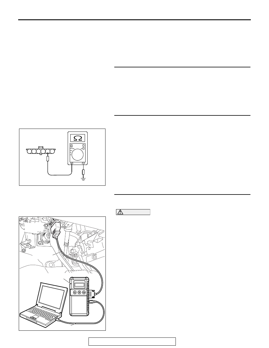
STEP 2. Check the continuity at accelerator pedal position 
sensor harness side connector C-123.
(1) Disconnect the connector C-123 and measure at the 

harness side.

(2) Measure the continuity between terminal No. 2 and ground.

• Should be less than 2 ohms.

Q: Does continuity exist?

YES : Go to Step 3.
NO :  Repair it. Then go to Step 4.

STEP 3. Using scan tool MB991958, check data list item 11: 
Accelerator Pedal Position Sensor (main).

CAUTION

To prevent damage to scan tool MB991958, always turn the 
ignition switch to the "LOCK" (OFF) position before con-
necting or disconnecting scan tool MB991958.
(1) Connect scan tool MB991958 to the data link connector.
(2) Turn the ignition switch to the "ON" position.
(3) Set scan tool MB991958 to the data reading mode for item 

11, Accelerator Pedal Position Sensor (main).

• Output voltage is between 0.9 and 1.1 volts when foot is 

released from accelerator pedal.

• Output voltage is 4.0 volts or higher when accelerator 

pedal is fully depressed.

(4) Turn the ignition switch to the "LOCK" (OFF) position.
Q: Is the sensor operating properly?

YES : Go to Step 4.
NO :  Replace the accelerator pedal position sensor. Then 

go to Step 4.

AK700281

1

6 5 4 3 2

AB

C-123 harness
connector:
component side

AK700568AB

MB991824

MB991827

MB991910

Data link
connector

MULTIPORT FUEL INJECTION (MFI) DIAGNOSIS

TSB Revision

MULTIPORT FUEL INJECTION (MFI) <3.0L ENGINE>

13B-678

STEP 4. Using scan tool MB991958, read the diagnostic 
trouble code (DTC).
(1) Connect scan tool MB991958 to the data link connector.
(2) Turn the ignition switch to the "ON" position.
(3) Read the DTC again.
(4) Turn the ignition switch to the "LOCK" (OFF) position.
Q: Is DTC P2123 set?

YES : Replace the ECM. When the ECM is replaced, 

register the ID code. Refer to GROUP 42B, Diagnosis 
− ID Codes Registration Judgment Table <Vehicles 

with KOS> 

P.42B-15

 or GROUP 42C, Diagnosis 

− ID 

Codes Registration Judgment Table <Vehicles with 
WCM> 

P.42C-10

.

NO :  It can be assumed that this malfunction is intermittent. 

Refer to GROUP 00, How to Use 
Troubleshooting/Inspection Service Points 

− How to 

Cope with Intermittent Malfunctions 

P.00-15

.

MULTIPORT FUEL INJECTION (MFI) DIAGNOSIS

TSB Revision

MULTIPORT FUEL INJECTION (MFI) <3.0L ENGINE>

13B-679

DTC P2127: Accelerator Pedal Position Sensor (sub) Circuit Low Input

.

CIRCUIT OPERATION

• A 5-volt power supply is applied on the accelera-

tor pedal position sensor (sub) power terminal 
(terminal No. 4) from the ECM (terminal No. 78).

• A voltage that is according to the accelerator 

opening angle is sent to the ECM (terminal No. 
77) from the accelerator pedal position sensor 
(sub) output terminal (terminal No. 6).

• The ground terminal (terminal No. 5) is grounded 

with ECM (terminal No. 79).

.

AK700163

71 72 73 74 75 76 77 78 79 80 81 82

83 84 85 86 87 88 89 90 91 92 93 94

95 96 97 98 99

100 101 102 103 104

112 113 114

109

108

107

110 111

115 116

106

105

118

117

6

1 2 3 4 5

AB

5 V

78

4

YELLO

W

-RED

YELLO

W

-BLUE

BLA

CK-WHITE

77

79

6

5

B-11

C-123

HALL IC

5 V

ACCELERATOR PEDAL POSITION SENSOR (SUB) CIRCUIT

ACCELERATOR
PEDAL POSITION
SENSOR (SUB)

ENGINE
CONTROL
MODULE

AK700431

AB

Accelerator pedal
position sensor

C-123 (B)

Connector: C-123

AK700402AB

ECM

B-11 (GR)

Connector: B-11

MULTIPORT FUEL INJECTION (MFI) DIAGNOSIS

TSB Revision

MULTIPORT FUEL INJECTION (MFI) <3.0L ENGINE>

13B-680

TECHNICAL DESCRIPTION

• The accelerator pedal position sensor (sub) out-

puts voltage which corresponds to the accelera-
tor pedal depression.

• The ECM checks whether the voltage is within a 

specified range.

.

DESCRIPTIONS OF MONITOR METHODS

Accelerator pedal position sensor (sub) output volt-

age is out of specified range.

.

MONITOR EXECUTION

Continuous

.

MONITOR EXECUTION CONDITIONS 
(Other monitor and Sensor)

Other Monitor (There is no temporary DTC stored 

in memory for the item monitored below)

• Not applicable

Sensor (The sensor below is determined to be 

normal)

• Not applicable

.

DTC SET CONDITIONS

Logic Flow Chart

.

Check Condition

• Ignition switch is "ON" position.

Judgement Criterion

• Accelerator pedal position sensor (sub) output 

voltage is 0.2 volt or less for 0.3 second.

.

OBD-II DRIVE CYCLE PATTERN

None.

.

TROUBLESHOOTING HINTS (The most 
likely causes for this code to be set are:)

• Accelerator pedal position sensor failed.

• Connector damage.

• Harness damage.

• ECM failed.

AK800588

Good

Malfunction

End

No

No

Output voltage <= 0.2V

Start

Yes

Yes

Continuous

failure for 0.3sec


Content   ..  934  935  936  937   ..