Mitsubishi Outlander GS45X. Manual - part 917


  Index      Mitsubishi     Mitsubishi Outlander GS45X - service repair manual


Search            


Content   ..  915  916  917  918   ..


Mitsubishi Outlander GS45X. Manual - part 917


MULTIPORT FUEL INJECTION (MFI) DIAGNOSIS

TSB Revision

MULTIPORT FUEL INJECTION (MFI) <3.0L ENGINE>

13B-601

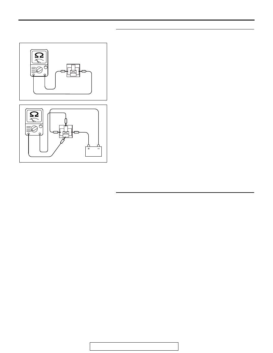
STEP 5. Check the MFI relay.
(1) Remove the MFI relay.
(2) Check for continuity between the MFI relay terminals No. 1 

and No. 3.

• There should be continuity.

(3) Use jumper wires to connect MFI relay terminal No. 3 to the 

positive battery terminal and terminal No. 1 to the negative 
battery terminal.

(4) Check for continuity between the MFI relay terminals No. 4 

and No. 2 while connecting and disconnecting the jumper 
wire at the negative battery terminal.

• Continuity (2 ohms or less) <Negative battery terminal 

connected>

• Should be open loop <Negative battery terminal discon-

nected>

(5) Install the MFI relay.
Q: Is the measured resistance within the specified range?

YES : Go to Step 6.
NO :  Replace the MFI relay. Then go to Step 8.

STEP 6. Check for short circuit to ground between MFI 
relay connector A-33X (terminal No. 1) and ECM connector 
B-11 (terminal No. 73).
Q: Is the harness wire in good condition?

YES : Go to Step 7.
NO :  Repair it. Then go to Step 8.

AK703903

1

3

2

4

AB

MFI relay side
connector

1

3

2

4

AK703904AB

MFI
relay side
connector 

MULTIPORT FUEL INJECTION (MFI) DIAGNOSIS

TSB Revision

MULTIPORT FUEL INJECTION (MFI) <3.0L ENGINE>

13B-602

STEP 7. Using scan tool MB991958, read the diagnostic 
trouble code (DTC).

CAUTION

To prevent damage to scan tool MB991958, always turn the 
ignition switch to the "LOCK" (OFF) position before con-
necting or disconnecting scan tool MB991958.
(1) Connect scan tool MB991958 to the data link connector.
(2) Turn the ignition switch to the "ON" position.
(3) After the DTC has been deleted, read the DTC again.
(4) Turn the ignition switch to the "LOCK" (OFF) position.
Q: Is DTC P0606 set?

YES : Replace the ECM. When the ECM is replaced, 

register the ID code. Refer to GROUP 42B, Diagnosis 
− ID Codes Registration Judgment Table <Vehicles 

with KOS> 

P.42B-15

 or GROUP 42C, Diagnosis 

− ID 

Codes Registration Judgment Table <Vehicles with 
WCM> 

P.42C-10

. Then go to Step 8.

NO :  It can be assumed that this malfunction is intermittent. 

Refer to GROUP 00, How to Use 
Troubleshooting/Inspection Service Points 

− How to 

Cope with Intermittent Malfunctions 

P.00-15

.

STEP 8. Using scan tool MB991958, read the diagnostic 
trouble code (DTC).
(1) Connect scan tool MB991958 to the data link connector.
(2) Turn the ignition switch to the "ON" position.
(3) After the DTC has been deleted, read the DTC again.
(4) Turn the ignition switch to the "LOCK"(OFF) position.
Q: Is DTC P0606 set?

YES : Retry the troubleshooting.
NO :  The inspection is complete.

DTC P060B: Internal Control Module A/D Processing Performance Problem

.

TECHNICAL DESCRIPTION

Monitors whether input voltage from the accelerator 
pedal position sensor (sub) is normally converted 
into a digital signal in the engine control module.

.

MONITOR EXECUTION

Continuous

.

MONITOR EXECUTION CONDITIONS 
(Other monitor and Sensor)

Other Monitor (There is no temporary DTC stored 

in memory for the item monitored below)

• Not applicable

Sensor (The sensor below is determined to be 

normal)

• Not applicable

.

AK700568AB

MB991824

MB991827

MB991910

Data link
connector

MULTIPORT FUEL INJECTION (MFI) DIAGNOSIS

TSB Revision

MULTIPORT FUEL INJECTION (MFI) <3.0L ENGINE>

13B-603

DTC SET CONDITIONS

Check Condition

• Ignition switch is "ON" position.

Judgment Criterion

• When the input voltage from the accelerator 

pedal position sensor (sub) is periodically 0 V for 
0.45 second, the digital value of the input voltage 
indicates 0.2 V or more.

.

OBD-II DRIVE CYCLE PATTERN

None.

.

TROUBLESHOOTING HINTS (The most 
likely causes for this code to be set are:)

• ECM failed.

DIAGNOSIS

Required Special Tools:

• MB991958: Scan Tool (M.U.T.-III Sub Assembly)

• MB991824: V.C.I.

• MB991827: USB Cable

• MB991910: Main Harness A

STEP 1. Using scan tool MB991958, read the diagnostic 
trouble code (DTC).

CAUTION

To prevent damage to scan tool MB991958, always turn the 
ignition switch to the "LOCK" (OFF) position before con-
necting or disconnecting scan tool MB991958.
(1) Connect scan tool MB991958 to the data link connector.
(2) Turn the ignition switch to the "ON" position.
(3) Read the DTC.
(4) Turn the ignition switch to the "LOCK" (OFF) position.
Q: Is DTC P060B set?

YES : Replace the ECM. When the ECM is replaced, 

register the ID code. Refer to GROUP 42B, Diagnosis 
− ID Codes Registration Judgment Table <Vehicles 

with KOS> 

P.42B-15

 or GROUP 42C, Diagnosis 

− ID 

Codes Registration Judgment Table <Vehicles with 
WCM> 

P.42C-10

.

NO :  It can be assumed that this malfunction is intermittent. 

Refer to GROUP 00, How to Use 
Troubleshooting/Inspection Service Points 

− How to 

Cope with Intermittent Malfunctions 

P.00-15

DTC P060D: Internal Control Module Accelerator Pedal Position Performance Problem

.

TECHNICAL DESCRIPTION

Compare the output value of the accelerator pedal 
position sensor (main) with that of the accelerator 
pedal position sensor (sub).

.

MONITOR EXECUTION

Continuous

.

MONITOR EXECUTION CONDITIONS 
(Other monitor and Sensor)

Other Monitor (There is no temporary DTC stored 

in memory for the item monitored below)

• Not applicable

AK700568AB

MB991824

MB991827

MB991910

Data link
connector

MULTIPORT FUEL INJECTION (MFI) DIAGNOSIS

TSB Revision

MULTIPORT FUEL INJECTION (MFI) <3.0L ENGINE>

13B-604

Sensor (The sensor below is determined to be 

normal)

• Not applicable

.

DTC SET CONDITIONS

Logic Flow Chart

Check Condition

• Change of accelerator pedal position sensor 

(sub) output voltage per 40 milliseconds is lower 
than 0.06 volt.

• Range/performance error of accelerator pedal 

position sensor (main and sub) circuit is not 
detected.

Judgment Criterion

• Voltage obtained with the formula given below is 

0.4 volt or higher for 0.5 second: accelerator 
pedal position sensor (main) output voltage 

− 

accelerator pedal position sensor (sub) output 
voltage.

NOTE: The accelerator pedal position sensor 
voltage used for the judgement is converted into 
the accelerator pedal position sensor voltage for 
the internal processing by the ECM.

.

OBD-II DRIVE CYCLE PATTERN

None.

.

TROUBLESHOOTING HINTS (The most 
likely causes for this code to be set are:)

• Accelerator pedal position sensor failed.

• ECM failed.

AK700543

Start

End

No

No

Yes

Yes

Yes

No

Malfunction

Good

Continuous

failure for 0.5sec

|APS (main)-APS (sub)|

>= 0.4V

Monitoring

conditions


Content   ..  915  916  917  918   ..