Mitsubishi Outlander GS45X. Manual - part 893


  Index      Mitsubishi     Mitsubishi Outlander GS45X - service repair manual


Search            


Content   ..  891  892  893  894   ..


Mitsubishi Outlander GS45X. Manual - part 893


MULTIPORT FUEL INJECTION (MFI) DIAGNOSIS

TSB Revision

MULTIPORT FUEL INJECTION (MFI) <3.0L ENGINE>

13B-505

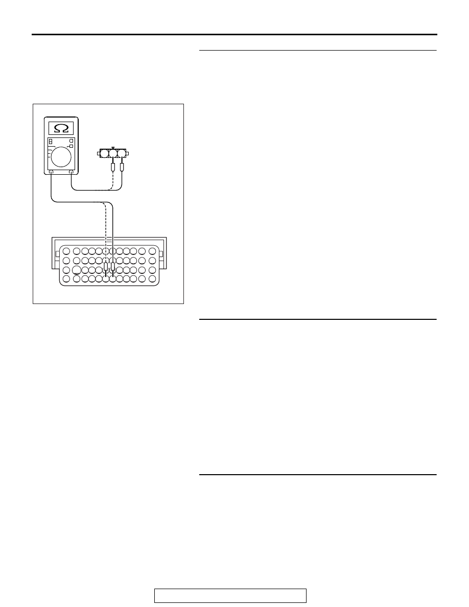
STEP 5. Check the harness wire between ECM connector 
B-11 and fuel tank differential pressure sensor connector 
D-19 for damage.
(1) Disconnect the connector B-11 and D-19 measure at the 

harness side.

(2) Measure the resistance between connector B-11 and 

connector D-19.

a. Connector B-11 (terminal No. 112) and connector D-19 

(terminal No. 1).

b. Connector B-11 (terminal No. 113) and connector D-19 

(terminal No. 2).

• Should be less than 2 ohms.

Q: Is the measured resistance less than 2 ohms?

YES : Go to Step 6 .
NO :  Repair the damaged harness wires. Then go to Step 7 

.

STEP 6. Replace the fuel tank differential pressure sensor.
(1) Replace the fuel tank differential pressure sensor.
(2) Carry out test drive with the drive cycle pattern. Refer to 

Diagnostic Function. OBD-II Drive Cycle. Pattern 5 

P.13B-11

.

(3) Check the diagnostic trouble code (DTC).
Q: Is DTC P0450 set?

YES : Replace the ECM. When the ECM is replaced, 

register the ID code. Refer to GROUP 42B, ID Code 
Registration Judgment Table <Vehicles with KOS> 

P.42B-15

 or GROUP 42C, ID Code Registration 

Judgment Table <Vehicles with WCM> 

P.42C-10

Then go to Step 7 .

NO :  The inspection is complete.

STEP 7. Perform the OBD-II drive cycle.
(1) Carry out a test drive with the drive cycle pattern. Refer to 

Diagnostic Function 

− OBD-II Drive Cycle − Pattern 5 

P.13B-11

.

(2) Check the diagnostic trouble code (DTC).
Q: Is DTC P0450 set?

YES : Repeat the troubleshooting.
NO :  The procedure is complete.

AK704175

82 81 80 79 78 77 76 75 74 73 72 71

94 93 92 91 90 89 88 87 86 85 84 83

99 98 97 96 95

100

101

102

103

104

105

106

112

113

114

109 108

107

110

111

115

116

117

118

1

2

3

D-19 harness connector:
component side 

B-11 harness connector:
component side 

AB

MULTIPORT FUEL INJECTION (MFI) DIAGNOSIS

TSB Revision

MULTIPORT FUEL INJECTION (MFI) <3.0L ENGINE>

13B-506

DTC P0451: Evaporative Emission Control System Pressure Sensor Range/Performance

AK901211

AB

I

A

C

E

D

F

G

H

Air filter

B

System diagram

Intake manifold

Evaporative emission
purge solenoid

Fuel tank

Evaporative
emission canister

Fuel tank differential
pressure sensor

Vent pipe

Evaporative emission
ventilation solenoid

MULTIPORT FUEL INJECTION (MFI) DIAGNOSIS

TSB Revision

MULTIPORT FUEL INJECTION (MFI) <3.0L ENGINE>

13B-507

71 72 73 74 75 76 77 78 79 80 81 82

83 84 85 86 87 88 89 90 91 92 93 94

95 96 97 98 99

100 101 102 103 104

112 113 114

109

108

107

110 111

115 116

106

105

118

117

2

8

7

6

5

4

3

11

21

20

19

18

17

16

15

14

13

12

9

22

1

10

3

2

1

AK704184

3

2

1

4

2

3

114

113

112

5 V

AB

D-19

(MU802723)

C-129

B-11

ENGINE 
CONTROL 
MODULE

FUEL TANK DIFFERENTIAL PRESSURE SENSOR CIRCUIT

FUEL TANK DIFFERENTIAL 
PRESSURE SENSOR

YELLO

W

-BLA

CK

YELLO

W

-BLA

CK

BR

O

W

N

B

R

O

WN

RED-GREEN

RED-GREEN

AK704190

ECM

B-11 (GR)

Connector: B-11

AB

AK900595

Connector: C-129

C-129

AB

MULTIPORT FUEL INJECTION (MFI) DIAGNOSIS

TSB Revision

MULTIPORT FUEL INJECTION (MFI) <3.0L ENGINE>

13B-508

.

CIRCUIT OPERATION

• The ECM (terminal No. 114) supplies a 5-volt ref-

erence signal to the fuel tank differential pressure 
sensor (terminal No. 3). The fuel tank differential 
pressure sensor (terminal No. 2) is grounded 
through the ECM (terminal No. 113).

• The fuel tank differential pressure sensor (termi-

nal No. 1) returns a voltage signal to the ECM 
(terminal No. 112) that is proportional to the pres-
sure in the fuel tank.

.

TECHNICAL DESCRIPTION

• The ECM monitors the fuel tank differential pres-

sure sensor signal voltage.

• The ECM determines whether the fuel tank differ-

ential pressure sensor signal voltage is within 
normal operating parameters.

.

DESCRIPTIONS OF MONITOR METHODS

• Detect malfunction if change of fuel tank differen-

tial pressure sensor output voltage during idling 
stays large during specified go/stop operations.

.

MONITOR EXECUTION

• Continuous.

.

MONITOR EXECUTION CONDITIONS 
(OTHER MONITOR AND SENSOR)

Other Monitor (There is no temporary DTC stored 

in memory for the item monitored below)

• Evaporative emission purge solenoid monitor

• Evaporative emission ventilation solenoid monitor

• Fuel temperature sensor monitor

• Fuel level sensor monitor

 Sensor (The sensors below are determined to be 

normal)

• Mass airflow sensor

• Barometric pressure sensor

• Intake air temperature sensor

• Engine coolant temperature sensor

• Accelerator pedal position sensor

.

AK704189

Fuel tank differential
pressure sensor

D-19

Connector: D-19

AB


Content   ..  891  892  893  894   ..