Mitsubishi Outlander GS45X. Manual - part 854


  Index      Mitsubishi     Mitsubishi Outlander GS45X - service repair manual


Search            


Content   ..  852  853  854  855   ..


Mitsubishi Outlander GS45X. Manual - part 854


MULTIPORT FUEL INJECTION (MFI) DIAGNOSIS

TSB Revision

MULTIPORT FUEL INJECTION (MFI) <3.0L ENGINE>

13B-349

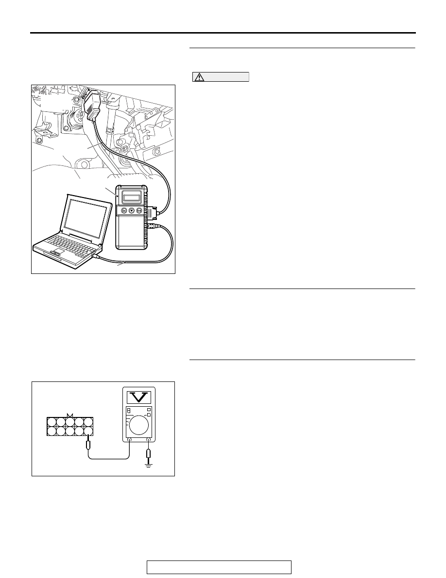
STEP 1. Using scan tool MB991958, check actuator test 
item 1: No. 1 Injector.

CAUTION

To prevent damage to scan tool MB991958, always turn the 
ignition switch to the "LOCK" (OFF) position before con-
necting or disconnecting scan tool MB991958.
(1) Connect scan tool MB991958 to the data link connector.
(2) Start the engine and run at idle.
(3) Set scan tool MB991958 to the actuator testing mode for 

item 1, No. 1 injector.

(4) Warm up the engine to normal operating temperature: 80

°C 

to 95

°C (176°F to 203°F).

• The idle should become slightly rougher.

(5) Turn the ignition switch to the "LOCK" (OFF) position.
Q: Is the actuator operating properly?

YES : It can be assumed that this malfunction is intermittent. 

Refer to GROUP 00, How to Use 
Troubleshooting/Inspection Service Points 

− How to 

Cope with Intermittent Malfunctions 

P.00-15

.

NO :  Go to Step 2.

STEP 2. Check for harness connector B- 21 at the 
intermediate connector and B-10 at the ECM for damage.
Q: Is the harness connector in good condition?

YES : Go to Step 3.
NO :  Repair it. Refer to GROUP 00E, Harness Connector 

Inspection 

P.00E-2

. Then go to Step 9.

STEP 3. Measure the injector supply voltage at the 
intermediate connector harness B-21 and ground.
(1) Disconnect the intermediate connector B-21 and measure 

at the female connector side.

(2) Turn the ignition switch to the "ON" position.
(3) Measure the voltage between terminal No. 6 and ground.

• Voltage should be battery positive voltage.

(4) Turn the ignition switch to the "LOCK" (OFF) position.
Q: Is the measured resistance battery positive voltage?

YES : Go to Step 4.
NO :  Check harness connector A-13 at intermediate 

connector for damage, and repair or replace as 
required. Refer to GROUP 00E, Harness Connector 
Inspection 

P.00E-2

. If intermediate connector is in 

good condition, repair harness wire between injector 
relay connector A-24X (terminal No. 3) and 
intermediate connector B-21 (terminal No. 6) because 
of open circuit. Then go to Step 9.

AK700568AB

MB991824

MB991827

MB991910

Data link
connector

3

4

5

8

9

1

2

6

7

10

AK700296AB

B-21 harness
connector:
harness side

MULTIPORT FUEL INJECTION (MFI) DIAGNOSIS

TSB Revision

MULTIPORT FUEL INJECTION (MFI) <3.0L ENGINE>

13B-350

STEP 4. Check the No. 1 cylinder injector resistance at 
intermediate connector B-21.
(1) Disconnect the intermediate connector B-21 and measure 

at male connector side.

(2) Measure the resistance between terminal No. 6 and No. 7.

• Resistance should be between 10.5 and 13.5 ohms.

Q: Is the measured resistance between 10.5 and 13.5 

ohms?
YES : 
Go to Step 7.
NO :  Go to Step 5.

STEP 5. Check the harness connector B-101 at No. 1 
cylinder injector for damage.
Remove the intake manifold.
Q: Is the harness connector in good condition?

YES : Go to Step 6.
NO :  Repair it. Refer to GROUP 00E, Harness Connector 

Inspection 

P.00E-2

. Then go to Step 9.

STEP 6. Check the No. 1 cylinder injector B-101.
(1) Disconnect the No. 1 cylinder injector connector B-101.
(2) Measure the resistance between injector side connector 

terminal No. 1 and No. 2.

Standard value: 10.5 

 13.5 ohms [at 20°C (68°F)]

Q: Is the measured resistance between 10.5 and 13.5 ohms 

[at 20

°C (68°F)]?

YES : Repair harness wire between the intermediate 

connector B-21 (terminal No. 6) and the injector 
connector B-101 (terminal No. 1) and harness 
wire between injector connector B-101 (terminal 
No. 2) and intermediate connector B-21 (terminal 
No. 7) because of open circuit or short circuit to 
ground or harness damage. 

Then go to Step 9.

NO :  Replace the No. 1 cylinder injector. Then go to Step 9.

5

4

3

2

1

10

9

8

7

6

AK700298AB

B-21
Intermediate
connector

AK700204

1 2

AB

Injector side
connector

MULTIPORT FUEL INJECTION (MFI) DIAGNOSIS

TSB Revision

MULTIPORT FUEL INJECTION (MFI) <3.0L ENGINE>

13B-351

STEP 7. Check for harness between the intermediate 
connector B-21and the ECM connector B-10.
(1) Disconnect the intermediate connector B-21 and the ECM 

connector B-10.

(2) Measure the resistance between the intermediate 

connector B-21 (terminal No. 7) and the ECM connector 
B-10 (terminal No. 2).

• Should be less than 2 ohms.

(3) Measure the continuity between the intermediate connector 

B-21 (terminal No. 7) and ground.

• Not continuity

Q: Is the harness wire in good condition?

YES : Go to Step 8.
NO :  Repair it. Refer to GROUP 00E, Harness Connector 

Inspection 

P.00E-2

. Then go to Step 9.

STEP 8. Using the oscilloscope, check the No. 1 cylinder 
injector.
(1) Disconnect the intermediate connector B-21 and connect 

the test harness MB991658 between the separated 
connectors.

(2) Connect the oscilloscope probe to injector intermediate 

connector terminal to No. 7.
NOTE: When measuring with the ECM side connector, dis-
connect all ECM connectors. Connect the check harness 
special tool (MB992110) between the separated connec-
tors. Then connect an oscilloscope probe to the check har-
ness connector terminal No. 2.

(3) Start the engine and run at idle.

(4) Measure the waveform.

• The waveform should show a normal pattern similar to 

the illustration.

(5) Turn the ignition switch to the "LOCK" (OFF) position.
Q: Is the waveform normal?

YES : It can be assumed that this malfunction is intermittent. 

Refer to 00, How to Use Troubleshooting/Inspection 
Service Points 

− How to Cope with Intermittent 

Malfunctions 

P.00-15

.

NO :  Replace the ECM. When the ECM is replaced, 

register the ID code. Refer to GROUP 42B, Diagnosis 
− ID Codes Registration Judgment Table <Vehicles 

with KOS> 

P.42B-15

 or GROUP 42C, Diagnosis 

− ID 

Codes Registration Judgment Table <Vehicles with 
WCM> 

P.42C-10

. Then go to Step 9.

AK700299

1

2

3

4

5

6

7

8

9

10

AB

B-21 harness
connector:
component side

5

4

3

2

1

10

9

8

7

6

AK700300AB

B-21 Intermediate
connector

MB991658

Oscilloscope

AK700301

Normal waveform

A: Injector drive time

A

AB

MULTIPORT FUEL INJECTION (MFI) DIAGNOSIS

TSB Revision

MULTIPORT FUEL INJECTION (MFI) <3.0L ENGINE>

13B-352

STEP 9. Test the OBD-II drive cycle.
(1) Carry out a test drive with the drive cycle pattern. Refer to 

Diagnostic Function 

− OBD-II Drive Cycle − Pattern 22 

P.13B-11

.

(2) Check the diagnostic trouble code (DTC).
Q: Is DTC P0201 set?

YES : Retry the troubleshooting.
NO :  The inspection is complete.


Content   ..  852  853  854  855   ..