Mitsubishi Outlander GS45X. Manual - part 808


  Index      Mitsubishi     Mitsubishi Outlander GS45X - service repair manual


Search            


Content   ..  806  807  808  809   ..


Mitsubishi Outlander GS45X. Manual - part 808


MULTIPORT FUEL INJECTION (MFI) DIAGNOSIS

TSB Revision

MULTIPORT FUEL INJECTION (MFI) <3.0L ENGINE>

13B-165

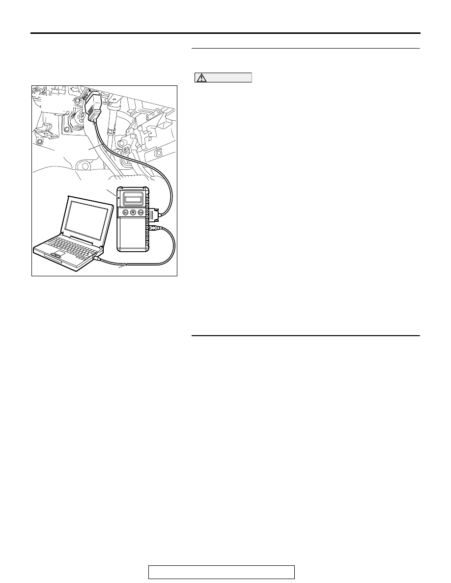
STEP 1. Using scan tool MB991958, check data list item 8: 
Manifold Absolute Pressure Sensor.

CAUTION

To prevent damage to scan tool MB991958, always turn the 
ignition switch to the "LOCK" (OFF) position before con-
necting or disconnecting scan tool MB991958.
(1) Connect scan tool MB991958 to the data link connector.
(2) Turn the ignition switch to the "ON" position.
(3) Set scan tool MB991958 to the data reading mode for item 

8, Manifold Absolute Pressure Sensor.

• When altitude is 0 m (0 foot), 101 kPa (29.8 in.Hg).

• When altitude is 600 m (1,969 feet), 95 kPa (28.1 in.Hg).

• When altitude is 1,200 m (3,937 feet), 88 kPa (26.0 

in.Hg).

• When altitude is 1,800 m (5,906 feet), 81 kPa (23.9 

in.Hg).

(4) Start the engine.

• When the engine is idling, 16 − 36 kPa (4.7 − 10.6 

in.Hg).

• When the engine is suddenly revved, manifold absolute 

pressure varies.

(5) Turn the ignition switch to the "LOCK" (OFF) position.
Q: Is the sensor operating properly?

YES : It can be assumed that this malfunction is intermittent. 

Refer to GROUP 00, How to Use 
Troubleshooting/Inspection Service Points 

− How to 

Cope with Intermittent Malfunctions 

P.00-15

.

NO :  Go to Step 2.

STEP 2. Check harness connector B-105 at the manifold 
absolute pressure sensor and harness connector B-10 at 
the ECM for damage.
Q: Is the harness connector in good condition?

YES : Go to Step 3.
NO :  Repair it. Refer to GROUP 00E, Harness Connector 

Inspection 

P.00E-2

. Then go to Step 5.

AK700568AB

MB991824

MB991827

MB991910

Data link
connector

MULTIPORT FUEL INJECTION (MFI) DIAGNOSIS

TSB Revision

MULTIPORT FUEL INJECTION (MFI) <3.0L ENGINE>

13B-166

STEP 3. Check the continuity at the manifold absolute 
pressure sensor connector B-105 and the ECM connector 
B-10 for damage.
(1) Disconnect the manifold absolute pressure sensor 

connector B-105 and the ECM connector B-10.

(2) Check for the continuity between the manifold absolute 

pressure sensor connector B-105 (terminal No. 3) and the 
ECM connector B-10 (terminal No. 46).

• Should be less than 2 ohms.

Q: Is the harness in good condition?

YES : Go to Step 4.
NO :  Repair it. Then go to step 5.

STEP 4. Replace the manifold absolute pressure sensor.
(1) Replace the manifold absolute pressure sensor.
(2) Carry out a test drive with the drive cycle pattern. Refer to 

Diagnostic Function 

− OBD-II Drive Cycle − Pattern 22 

P.13B-11

.

(3) Check the diagnostic trouble code (DTC).
Q: Is DTC P0108 set?

YES : Replace the ECM. When the ECM is replaced, 

register the ID code. Refer to GROUP 42B, Diagnosis 
− ID Codes Registration Judgment Table <Vehicles 

with KOS> 

P.42B-15

 or GROUP 42C, Diagnosis 

− ID 

Codes Registration Judgment Table <Vehicles with 
WCM> 

P.42C-10

. Then go to Step 5.

NO :  The inspection is complete.

STEP 5. Test the OBD-II drive cycle.
(1) Carry out a test drive with the drive cycle pattern. Refer to 

Diagnostic Function 

− OBD-II Drive Cycle − Pattern 22 

P.13B-11

.

(2) Check the diagnostic trouble code (DTC).
Q: Is DTC P0108 set?

YES : Retry the troubleshooting.
NO :  The inspection is complete.

AK900594

16 15 14 13 12 11 10 9 8 7 6 5 4 3

2

1

32 31 30 29 28 27 26 25 24 23 22 21 20 19 18 17

48 47 46 45 44 43 42 41 40 39 38 37 36 35 34 33

64 63 62 61 60 59 58 57 56 55 54 53 52 51 50 49

3 2 1

AB

B-105 harness
connector:
component side 

B-10 harness
connector:
component side 

MULTIPORT FUEL INJECTION (MFI) DIAGNOSIS

TSB Revision

MULTIPORT FUEL INJECTION (MFI) <3.0L ENGINE>

13B-167

DTC P0111: Intake Air Temperature Circuit Range/Performance Problem

.

CIRCUIT OPERATION

• Approximately 5 volts are applied to the intake air 

temperature sensor output terminal (terminal No. 
1) from the ECM (terminal No. 89) via the resistor 
in the ECM. The ground terminal (terminal No. 4) 
is grounded with ECM (terminal No. 88).

• The intake air temperature sensor is a negative 

temperature coefficient type of resistor. When the 
intake air temperature rises, the resistance 
decreases.

• The intake air temperature sensor output voltage 

increases when the resistance increases and 
decreases when the resistance decreases.

.

TECHNICAL DESCRIPTION

• The intake air temperature sensor converts the 

intake air temperature to a voltage.

• The ECM checks whether this voltage is within a 

specified range.

.

DESCRIPTIONS OF MONITOR METHODS

Intake air temperature sensor output voltage does 

not change when specified go/stop operations 
are repeated.

AK700135

71 72 73 74 75 76 77 78 79 80 81 82

83 84 85 86 87 88 89 90 91 92 93 94

95 96 97 98 99

100 101 102 103 104

112 113 114

109

108

107

110 111

115 116

106

105

118

117

3 4

2

1

AB

88

89

4

1

5 V

INTAKE AIR TEMPERATURE SENSOR CIRCUIT

INTAKE AIR TEMPERATURE
SENSOR (INTEGRATED IN
MASS AIRFLOW SENSOR)

VIOLET

BLA

CK-WHITE

A-07

(MU805110)

B-11

ENGINE
CONTROL
MODULE

AK700406

AB

Mass airflow
sensor

A-07 (GR)

Connector: A-07

AK700402AB

ECM

B-11 (GR)

Connector: B-11

MULTIPORT FUEL INJECTION (MFI) DIAGNOSIS

TSB Revision

MULTIPORT FUEL INJECTION (MFI) <3.0L ENGINE>

13B-168

.

MONITOR EXECUTION

Continuous

.

MONITOR EXECUTION CONDITIONS 
(Other monitor and Sensor)

Other Monitor (There is no temporary DTC stored 

in memory for the item monitored below)

• Not applicable

Sensor (The sensor below is determined to be 

normal)

• Engine coolant temperature sensor

.

DTC SET CONDITIONS

Logic Flow Chart

.

Check Conditions

• Engine coolant temperature is higher than 76°C 

(169

°F).

• Repeat 2 or more times: drive

*1

, stop

*2

.

• Drive

*1

: vehicle speed higher than 50 km/h 

(31 mph) lasting a total of more than 60 sec-
onds.

• Stop

*2

: vehicle speed lower than 1.5 km/h (1.0 

mph) lasting more than 30 seconds.

End

Malfunction

Yes

Yes

No

No

Yes

No

Go/stop operation

for specified times

Intake air temp.

changes

Monitoring

conditions

Good

Start

AK604314


Content   ..  806  807  808  809   ..