Mitsubishi Outlander GS45X. Manual - part 797


  Index      Mitsubishi     Mitsubishi Outlander GS45X - service repair manual


Search            


Content   ..  795  796  797  798   ..


Mitsubishi Outlander GS45X. Manual - part 797


MULTIPORT FUEL INJECTION (MFI) DIAGNOSIS

TSB Revision

MULTIPORT FUEL INJECTION (MFI) <3.0L ENGINE>

13B-121

STEP 1. Check harness connector A-33X at the MFI relay, 
harness connector B-14 at the left bank heated oxygen 
sensor (front) and harness connector B-10 at the ECM for 
damage.
Q: Is the harness connector in good condition?

YES : Go to Step 2.
NO :  Repair or replace it. Refer to GROUP 00E, Harness 

Connector Inspection 

P.00E-2

. Then go to Step 6.

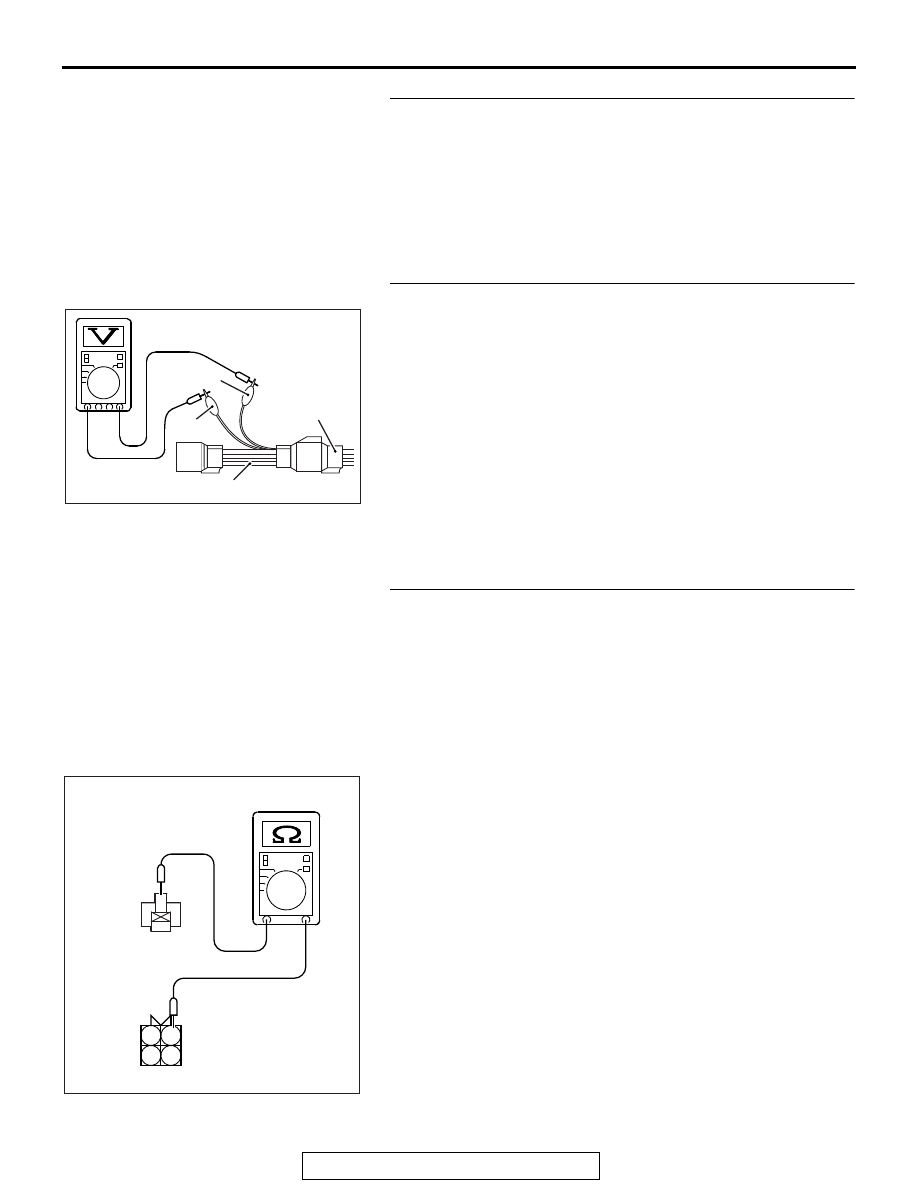
STEP 2. Check the left bank heated oxygen sensor (front).
(1) Disconnect left bank heated oxygen sensor (front) 

connector B-14 and connect test harness special tool, 
MD998464, to the connector on the left bank heated oxygen 
sensor (front) side.

(2) Measure the resistance between left bank heated oxygen 

sensor (front) connector terminal No. 1 (red clip) and 
terminal No. 3 (blue clip).

Standard value: 4.5 

 8.0 Ω [at 20°C (68°F)]

Q: Is the measured resistance between 4.5 and 8.0 ohms 

[at 20

°C (68°F)]?

YES : Go to Step 3.
NO :  Replace the left bank heated oxygen sensor (front). 

Then go to Step 6.

STEP 3. Check for harness damage between MFI relay 
connector A-33X and left bank heated oxygen sensor 
(front) connector B-14.
NOTE: Check harness after checking intermediate connector 
A-13. If intermediate connector is damaged, repair or replace it. 
Refer to GROUP 00E, Harness Connector Inspection 

P.00E-2

Then go to Step 6 .
(1) Disconnect the MFI relay connector A-33X and the left bank 

heated oxygen sensor (front) connector B-14.

(2) Measure the resistance between the MFI relay connector 

A-33X (terminal No. 2) and the left bank heated oxygen 
sensor (front) connector B-14 (terminal No. 1).

• Should be less than 2 ohms.

Q: Is the harness wire in good condition?

YES : Go to Step 4.
NO :  Repair it. Then go to Step 6.

AK700179

MD998464

Red

Blue

AB

Heated
oxygent
sensor
component
side
connector

AKA00834

3

1

2

4

1

2

3

4

B-14 harness
connector:
component side 

A-33X harness
connector:
component side

AB

MULTIPORT FUEL INJECTION (MFI) DIAGNOSIS

TSB Revision

MULTIPORT FUEL INJECTION (MFI) <3.0L ENGINE>

13B-122

STEP 4. Check for harness damage between left bank 
heated oxygen sensor (front) connector B-14 and ECM 
connector B-10.
(1) Disconnect the left bank heated oxygen sensor (front) 

connector B-14 and the ECM connector B-10.

(2) Measure the resistance between the left bank heated 

oxygen sensor (front) connector B-14 (terminal No. 3) and 
the ECM connector B-10 (terminal No. 34).

• Should be less than 2 ohms.

Q: Is the harness wire in good condition?

YES : Go to Step 5.
NO :  Repair it. Then go to Step 6.

STEP 5. Check the trouble symptoms.
(1) Carry out a test drive with the drive cycle pattern. Refer to 

Diagnostic Function 

− OBD-II Drive Cycle − Pattern 2 

P.13B-11

.

(2) Check the diagnostic trouble code (DTC).
Q: Is DTC P0059 set?

YES : Replace the ECM. When the ECM is replaced, 

register the ID code. Refer to GROUP 42B, Diagnosis 
− ID Codes Registration Judgment Table <Vehicles 

with KOS> 

P.42B-15

 or GROUP 42C, Diagnosis 

− ID 

Codes Registration Judgment Table <Vehicles with 
WCM> 

P.42C-10

. Then go to Step 6.

NO :  It can be assumed that this malfunction is intermittent. 

Refer to GROUP 00, How to Use 
Troubleshooting/Inspection Service Points 

− How to 

Cope with Intermittent Malfunctions 

P.00-15

.

STEP 6. Test the OBD-II drive cycle.
(1) Carry out a test drive with the drive cycle pattern. Refer to 

Diagnostic Function 

− OBD-II Drive Cycle − Pattern 2 

P.13B-11

.

(2) Check the diagnostic trouble code (DTC).
Q: Is DTC P0059 set?

YES : Retry the troubleshooting.
NO :  The inspection is complete.

AK700187

1

2

3

4

16 15 14 13 12 11 10 9 8 7 6 5 4 3

2

1

32 31 30 29 28 27 26 25 24 23 22 21 20 19 18 17

48 47 46 45 44 43 42 41 40 39 38 37 36 35 34 33

64 63 62 61 60 59 58 57 56 55 54 53 52 51 50 49

B-14 harness connector:
component side 

B-10 harness connector:
component side 

AB

MULTIPORT FUEL INJECTION (MFI) DIAGNOSIS

TSB Revision

MULTIPORT FUEL INJECTION (MFI) <3.0L ENGINE>

13B-123

DTC P0068: Mass Airflow Sensor Plausibility

.

TECHNICAL DESCRIPTION

Compare the actual measurement of volumetric effi-
ciency by a mass airflow sensor signal with volumet-
ric efficiency estimated from a throttle position 
sensor (main or sub) signal.

.

MONITOR EXECUTION

Continuous

.

MONITOR EXECUTION CONDITIONS 
(Other monitor and Sensor)

Other Monitor (There is no temporary DTC stored 

in memory for the item monitored below)

• Not applicable

Sensor (The sensor below is determined to be 

normal)

• Not applicable

.

MULTIPORT FUEL INJECTION (MFI) DIAGNOSIS

TSB Revision

MULTIPORT FUEL INJECTION (MFI) <3.0L ENGINE>

13B-124

DTC SET CONDITIONS

Logic Flow Chart

Check Conditions

• The plausibility error of the throttle position sen-

sor (main) is detected.

• The plausibility error of the throttle position sen-

sor (sub) is detected.

Judgment Criterion

• For 0.36 second, the difference between the volu-

metric efficiency estimated by the (main) throttle 
position sensor and the volumetric efficiency esti-
mated by the (sub) throttle position sensor is 8.8 
% or less.

.

OBD-II DRIVE CYCLE PATTERN

Refer to Diagnostic Function 

− OBD-II Drive Cycle 

Pattern 17 

P.13B-11

.

.

TROUBLESHOOTING HINTS (The most 
likely causes for this code to be set are:)

• Mass airflow sensor system failed.

• Intake system vacuum leak.

• There is some foreign matter around mass air-

flow sensor.

• ECM failed.

AK800586

Start

Yes

Yes

Yes

No

No

No

Continuous failure

for specified time

Malfunction

End

Good

Monitoring
conditions

|Calculated Ec {TPS (main)}

-calculated Ec {TPS (sub)}| 

< 8.8 percent


Content   ..  795  796  797  798   ..