Mitsubishi Outlander GS45X. Manual - part 787
MULTIPORT FUEL INJECTION (MFI) DIAGNOSIS
TSB Revision
MULTIPORT FUEL INJECTION (MFI) <3.0L ENGINE>
13B-81
.
CIRCUIT OPERATION
• Power is supplied from the MFI relay (terminal
No. 2) to the right bank heated oxygen sensor
(rear) heater.
• The ECM (terminal No. 49) controls continuity to
the right bank heated oxygen sensor (rear)
heater by turning the power transistor in the ECM
"ON" and "OFF".
.
TECHNICAL DESCRIPTION
• The ECM checks whether the heater current is
within a specified range when the heater is ener-
gized.
.
DESCRIPTIONS OF MONITOR METHODS
Right bank heated oxygen sensor heater (rear) cur-
rent is out of specified range.
.
MONITOR EXECUTION
Continuous
.
MONITOR EXECUTION CONDITIONS
(Other monitor and Sensor)
Other Monitor (There is no temporary DTC stored
in memory for the item monitored below)
• Not applicable
Sensor (The sensor below is determined to be
normal)
• Not applicable
.
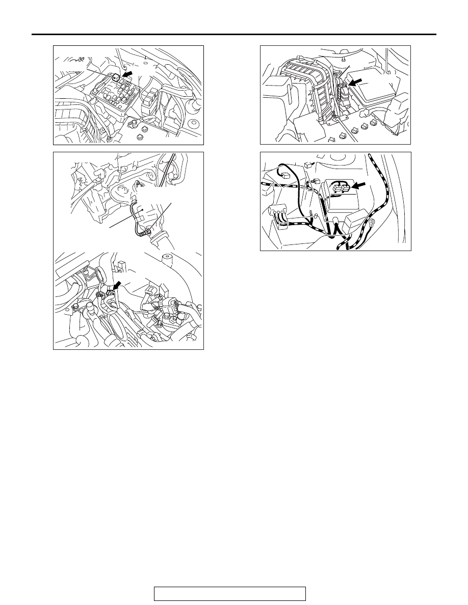
AK700399AB
MFI relay
A-33X
Connector: A-33X
AK900130AD
Right bank heated
oxygen sensor (rear)
Front exhaust
pipe RH
B-02 (B)
Connector: B-02
AK700401AB
ECM
B-10 (GR)
Connector: B-10
AK900602
Connector: A-13
A-13
AB