Mitsubishi Outlander GS45X. Manual - part 730


  Index      Mitsubishi     Mitsubishi Outlander GS45X - service repair manual


Search            


Content   ..  728  729  730  731   ..


Mitsubishi Outlander GS45X. Manual - part 730


MULTIPORT FUEL INJECTION (MFI) DIAGNOSIS

TSB Revision

MULTIPORT FUEL INJECTION (MFI) <2.4L ENGINE>

13A-743

STEP 4. Using scan tool MB991958, check data list.
(1) Turn the ignition switch to the "ON" position.
(2) Check the following items in the data list. Refer to Data List 

Reference Table 

P.13A-818

.

a. Item 5: Intake Air Temperature Sensor.
b. Item 6: Engine Coolant Temperature Sensor.

c. Item 10: Mass Airflow Sensor

d. Item 36: Intake V.V.T. phase angle
e. Item 39: Exhaust V.V.T. phase angle

f. Item 76: A/C Switch

(3) Turn the ignition switch to the "LOCK" (OFF) position.
Q: Are they operating properly?

YES : Go to Step 5.
NO :  Repair or replace it. Then confirm that the malfunction 

symptom is eliminated.

STEP 5. Check the fuel pressure.
Refer to Fuel Pressure Test 

P.13A-868

.

Q: Is the fuel pressure normal?

YES : Go to Step 6.
NO :  Repair or replace it. Then confirm that the malfunction 

symptom is eliminated.

STEP 6. Check the ignition timing.
Refer to GROUP 11A, On-vehicle Service 

− Ignition Timing 

Check 

P.11A-13

.

Q: Is the ignition timing normal?

YES : Go to Step 7.
NO :  Check for installed conditions of the timing chain. 

Then confirm that the malfunction symptom is 
eliminated.

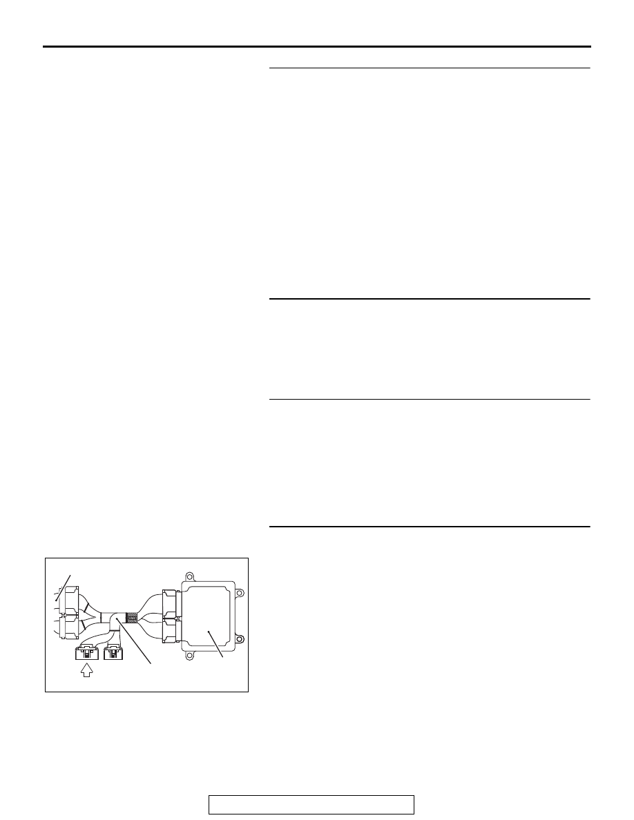
STEP 7. Measure the voltage at ECM connector B-10 by 
using check harness special tool MB992110.
(1) Disconnect all ECM connectors. Connect the check 

harness special tool MB992110 between the separated 
connectors.

(2) Start the engine and run at idle.

NOTE: Vehicles for Canada, the headlight, taillight, etc. 
remain lit even when the lighting switch is in "OFF" position 
but this is no problem for checks.

AK604040

ECM

AB

Body side harness 

MB992110

MULTIPORT FUEL INJECTION (MFI) DIAGNOSIS

TSB Revision

MULTIPORT FUEL INJECTION (MFI) <2.4L ENGINE>

13A-744

(3) Measure the voltage between terminal No. 60 and ground.

a. Engine: warming up, idling
b. Radiator fan: stopped

c. Headlight: OFF to ON

d. Stop light: OFF to ON
e. Rear defogger switch: OFF to ON

• Voltage increases

(4) Turn the ignition switch to the "LOCK" (OFF) position.
Q: Is the harness measured voltage within the specified 

range?
YES : 
Go to Step 8.
NO :  Replace the generator. Then confirm that the 

malfunction symptom is eliminated.

STEP 8. Check the spark plugs.
Refer to GROUP 16, Ignition System 

− On-vehicle Service − 

Spark Plug Check And Cleaning 

P.16-45

.

Q: Are there any abnormalities?

YES : Replace the spark plug. Then confirm that the 

malfunction symptom is eliminated.

NO :  Go to Step 9.

STEP 9. Check the ignition coil.
(1) Remove the intake manifold.
(2) Refer to GROUP 16, Ignition System 

− On-vehicle Service 

− Ignition Coil Check And Cleaning 

P.16-44

.

Q: Are there any abnormalities?

YES : Replace the ignition coil. Then confirm that the 

malfunction symptom is eliminated.

NO :  Go to Step 10.

STEP 10. Check the compression pressure.
Refer to GROUP 11A, On-vehicle Service 

− Compression 

Pressure Check 

P.11A-18

.

Q: Is the compression pressure normal?

YES : Go to Step 11.
NO :  Repair it. Then confirm that the malfunction symptom 

is eliminated.

AK604041

16 15 14 13 12 11 10 9 8 7 6 5 4 3

2

1

32 31 30 29 28 27 26 25 24 23 22 21 20 19 18 17

48 47 46 45 44 43 42 41 40 39 38 37 36 35 34 33

64 63 62 61 60 59 58 57 56 55 54 53 52 51 50 49

AC

Power plant ECU
check harness connector

MULTIPORT FUEL INJECTION (MFI) DIAGNOSIS

TSB Revision

MULTIPORT FUEL INJECTION (MFI) <2.4L ENGINE>

13A-745

STEP 11. Check the positive crankcase ventilation system.
Refer to GROUP 17, Emission Control System 

− Positive 

Crankcase Ventilation System 

− Positive Crankcase Ventilation 

System Check 

P.17-74

.

Q: Is the positive crankcase ventilation system?

YES : Go to Step 12.
NO :  Repair it. Then confirm that the malfunction symptom 

is eliminated.

STEP 12. Check the purge control system.
Refer to GROUP 17, Emission Control System 

− Evaporative 

Emission Control System 

− Purge Control System Check 

(Purge Flow Check) 

P.17-77

.

Q: Is the purge control system normal?

YES : Check the following items, and repair or replace the 

defective items.

1. Vacuum leak.
2. Check if fuel is contaminated.
3. Check if the injectors are clogged.

Then confirm that the malfunction symptom is 

eliminated.

NO :  Repair it. Then confirm that the malfunction symptom 

is eliminated.

Inspection procedure 8: Idle speed is high (improper idle speed)

.

COMMENT

• In such cases as the above, the cause is proba-

bly that the intake air volume during idle is too 
great.

.

TROUBLESHOOTING HINTS (The most 
likely causes for this case:)

• Malfunction of the engine coolant temperature 

sensor signal.

• Malfunction of the accelerator pedal position sen-

sor (main) signal.

• Malfunction of the accelerator pedal position sen-

sor (sub) signal.

• Malfunction of the A/C switch signal.

• Malfunction of the power steering pressure switch 

signal.

• Malfunction of the evaporative emission control 

system.

• Malfunction of the ECM.

DIAGNOSIS

Required Special Tools:

• MB991958: Scan Tool (M.U.T.-III Sub Assembly)

• MB991824: V.C.I.

• MB991827: USB Cable

• MB991910: Main Harness A

MULTIPORT FUEL INJECTION (MFI) DIAGNOSIS

TSB Revision

MULTIPORT FUEL INJECTION (MFI) <2.4L ENGINE>

13A-746

STEP 1. Using scan tool MB991958, read the diagnostic 
trouble code (DTC).

CAUTION

To prevent damage to scan tool MB991958, always turn the 
ignition switch to the "LOCK" (OFF) position before con-
necting or disconnecting scan tool MB991958.
(1) Connect scan tool MB991958 to the data link connector.
(2) Turn the ignition switch to the "ON" position.
(3) Read the DTC.
(4) Turn the ignition switch to the "LOCK" (OFF) position.
Q: Is any DTC set?

YES : Refer to Diagnostic Trouble Code Chart 

P.13A-49

.

NO :  Go to Step 2.

STEP 2. Using scan tool MB991958, check data list.
(1) Turn the ignition switch to the "ON" position.
(2) Check the following item in the data list. Refer to Data List 

Reference Table 

P.13A-818

.

a. Item 6: Engine Coolant Temperature Sensor.
b. Item 11: Accelerator pedal position sensor (main)

c. Item 12: Accelerator pedal position sensor (sub)

d. Item 76: A/C switch
e. Item 83: Power steering pressure switch

(3) Turn the ignition switch to the "LOCK" (OFF) position.
Q: Is the sensor operating properly?

YES : Refer to GROUP 17, Emission Control System 

− 

Evaporative Emission Control System 

− Evaporative 

Emission Purge Solenoid Check 

P.17-78

.

NO :  Repair or replace it. Then confirm that the malfunction 

symptom is eliminated.

AK700568AB

MB991824

MB991827

MB991910

Data link
connector


Content   ..  728  729  730  731   ..