Mitsubishi Outlander GS45X. Manual - part 726


  Index      Mitsubishi     Mitsubishi Outlander GS45X - service repair manual


Search            


Content   ..  724  725  726  727   ..


Mitsubishi Outlander GS45X. Manual - part 726


MULTIPORT FUEL INJECTION (MFI) DIAGNOSIS

TSB Revision

MULTIPORT FUEL INJECTION (MFI) <2.4L ENGINE>

13A-727

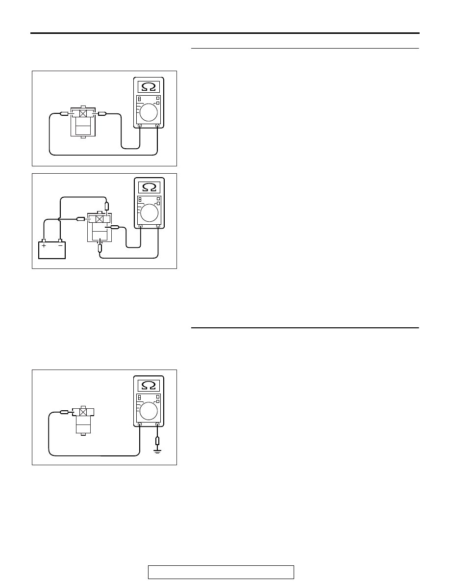
STEP 6. Check the injector relay.
(1) Remove the injector relay.
(2) Check for continuity between the injector relay terminal No. 

1 and No. 2.
There should be continuity.

(3) Use jumper wires to connect injector relay terminal No. 1 to 

the positive battery terminal and terminal No. 2 to the 
negative battery terminal.

(4) Check for continuity between the injector relay terminal No. 

3 and No. 4 while connecting and disconnecting the jumper 
wire at the negative battery terminal.

• Continuity (2 ohms or less). <Negative battery terminal 

connected>

• Should be open loop. <Negative battery terminal discon-

nected>

(5) Install the injector relay.
Q: Is the measured resistance normal?

YES : Go to Step 7.
NO :  Replace the injector relay. Then confirm that the 

malfunction symptom is eliminated.

STEP 7. Check for continuity at injector relay harness side 
connector A-24X.
(1) Disconnect the connector A-24X and measure at the 

harness side.

(2) Check for the continuity between terminal No. 2 and 

ground.

• Continuity (2 ohms or less).

Q: Does continuity exist?

YES : Go to Step 8.
NO :  Repair harness wire between injector relay connector 

A-24X (terminal No. 2) and ground because of open 
circuit or harness damage. Then confirm that the 
malfunction symptom is eliminated.

AK604033

1

2

3
4

Injector relay side connector

AB

AK604034

1

2

3
4

AB

Injector relay side connector

AK604037

2

1

3
4

AC

A-24X harness
connector:
component side

MULTIPORT FUEL INJECTION (MFI) DIAGNOSIS

TSB Revision

MULTIPORT FUEL INJECTION (MFI) <2.4L ENGINE>

13A-728

STEP 8. Measure the power supply voltage at injector relay 
harness side connector A-24X.
(1) Disconnect the connector A-24X and measure at the 

harness side.

(2) Turn the ignition switch to the "ON" position.
(3) Measure the voltage between terminal No. 1 and ground.

• Voltage should be battery positive voltage.

Q: Is battery positive voltage (approximately 12 volts) 

present?
YES : 
Go to Step 10.
NO :  Go to Step 9.

STEP 9. Check harness connector C-304 at ETACS-ECU for 
damage.
Q: Is the harness connector in good condition?

YES : Repair harness wire between injector relay connector 

A-24X (terminal No. 1) and ETACS-ECU connector 
C-304 (terminal No. 10) because of open circuit or 
short circuit to ground. Then confirm that the 
malfunction symptom is eliminated.

NO :  Repair or replace it. Refer to GROUP 00E, Harness 

Connector Inspection 

P.00E-2

. Then confirm that the 

malfunction symptom is eliminated.

STEP 10. Measure the power supply voltage at injector 
relay harness side connector A-24X.
(1) Disconnect the connector A-24X and measure at the 

harness side.

(2) Turn the ignition switch to the "ON" position.
(3) Measure the voltage between terminal No. 4 and ground.

• Voltage should be battery positive voltage.

Q: Is battery positive voltage (approximately 12 volts) 

present?
YES : 
Go to Step 12.
NO :  Go to Step 11.

AK604036

2

1

3
4

AC

A-24X harness
connector:
component side

2

1

3
4

AK604035 AC

A-24X harness
connector:
component side

MULTIPORT FUEL INJECTION (MFI) DIAGNOSIS

TSB Revision

MULTIPORT FUEL INJECTION (MFI) <2.4L ENGINE>

13A-729

STEP 11. Check harness connector A-33X at MFI relay for 
damage.
Q: Is the harness connector in good condition?

YES : Repair harness wire between MFI relay connector 

A-33X (terminal No. 2) and injector relay 
connector A-24X (terminal No. 4) because of open 
circuit or short circuit to ground. Then confirm that 
the malfunction symptom is eliminated.

NO :  Repair or replace it. Refer to GROUP 00E, Harness 

Connector Inspection 

P.00E-2

. Then confirm that the 

malfunction symptom is eliminated.

STEP 12. Check for open circuit and short circuit to 
ground between injector relay connector and injector 
connector.
NOTE: Check harness connector after checking intermediate 
connector A-13. If intermediate connector is damaged, repair or 
replace it. Refer to GROUP 00E, Harness Connector Inspec-
tion 

P.00E-2

. Then confirm that the malfunction symptom is 

eliminated.

a. Injector relay connector A-24X (terminal No. 3) and No. 1 

cylinder injector connector B-101 (terminal No. 1).

b. Injector relay connector A-24X (terminal No. 3) and No. 2 

cylinder injector connector B-120 (terminal No. 1).

c. Injector relay connector A-24X (terminal No. 3) and No. 3 

cylinder injector connector B-103 (terminal No. 1).

d. Injector relay connector A-24X (terminal No. 3) and No. 4 

cylinder injector connector B-116 (terminal No. 1).

Q: Is the harness wire in good condition?

YES : Go to Step 13.
NO :  Repair it. Then confirm that the malfunction symptom 

is eliminated.

STEP 13. Check harness connector C-304 at ETACS-ECU 
for damage.
Q: Is the harness connector in good condition?

YES : Repair harness wire between injector relay connector 

A-24X (terminal No. 1) and ETACS-ECU connector 
C-304 (terminal No. 10) because of harness damage. 
Then confirm that the malfunction symptom is 
eliminated.

NO :  Repair or replace it. Refer to GROUP 00E, Harness 

Connector Inspection 

P.00E-2

. Then confirm that the 

malfunction symptom is eliminated.

MULTIPORT FUEL INJECTION (MFI) DIAGNOSIS

TSB Revision

MULTIPORT FUEL INJECTION (MFI) <2.4L ENGINE>

13A-730

STEP 14. Check harness connector A-33X at MFI relay for 
damage.
Q: Is the harness connector in good condition?

YES : Go to Step 15.
NO :  Repair or replace it. Refer to GROUP 00E, Harness 

Connector Inspection 

P.00E-2

. Then confirm that the 

malfunction symptom is eliminated.

STEP 15. Check for harness damage between MFI relay 
connector A-33X (terminal No. 2) and injector relay 
connector A-24X (terminal No. 4).
Q: Is the harness wire in good condition?

YES : Go to Step 16.
NO :  Repair it. Then confirm that the malfunction symptom 

is eliminated.

STEP 16. Check for harness damage between injector 
relay connector and injector connector.
NOTE: Check harness after checking intermediate connector 
A-13. If intermediate connector is damaged, repair or replace it. 
Refer to GROUP 00E, Harness Connector Inspection 

P.00E-2

Then confirm that the malfunction symptom is eliminated.

a. Injector relay connector A-24X (terminal No. 3) and No. 1 

cylinder injector connector B-101 (terminal No. 1).

b. Injector relay connector A-24X (terminal No. 3) and No. 2 

cylinder injector connector B-120 (terminal No. 1).

c. Injector relay connector A-24X (terminal No. 3) and No. 3 

cylinder injector connector B-103 (terminal No. 1).

d. Injector relay connector A-24X (terminal No. 3) and No. 4 

cylinder injector connector B-116 (terminal No. 1).

Q: Is the harness wire in good condition?

YES : Go to Step 17.
NO :  Repair it. Then confirm that the malfunction symptom 

is eliminated.

STEP 17. Using scan tool MB991958, check data list.
(1) Turn the ignition switch to the "ON" position.
(2) Check the following items in the data List. Refer to Data List 

Reference Table 

P.13A-818

.

a. Item 1: Power Supply Voltage

(3) Turn the ignition switch to the "LOCK" (OFF) position.
Q: Are they operating properly?

YES : Go to Step 18.
NO :  Repair or replace it. Then confirm that the malfunction 

symptom is eliminated.


Content   ..  724  725  726  727   ..