Mitsubishi Outlander GS45X. Manual - part 696


  Index      Mitsubishi     Mitsubishi Outlander GS45X - service repair manual


Search            


Content   ..  694  695  696  697   ..


Mitsubishi Outlander GS45X. Manual - part 696


MULTIPORT FUEL INJECTION (MFI) DIAGNOSIS

TSB Revision

MULTIPORT FUEL INJECTION (MFI) <2.4L ENGINE>

13A-607

.

CIRCUIT OPERATION

• A 5-volt voltage is supplied to the battery current 

sensor power terminal (terminal No. 1) from the 
ECM (terminal No. 99). The ground terminal (ter-
minal No. 3) is grounded with ECM (terminal No. 
101).

• A voltage that is proportional to the battery cur-

rent is sent to the ECM (terminal No. 100) from 
the battery current sensor output terminal (termi-
nal No. 4).

.

TECHNICAL DESCRIPTION

• The battery current sensor outputs a voltage 

which corresponds to the battery current.

• The ECM checks whether this voltage is within a 

specified range.

.

DESCRIPTIONS OF MONITOR METHODS

Battery current sensor output voltage is out of speci-
fied range.

.

DTC SET CONDITIONS

Check Condition

• Ignition switch is "ON" position

Judgement Criterion

• The battery current sensor output voltage is less 

than 0.2 V for 2 seconds.

or

• The battery current sensor output voltage is more 

than 4.8 V for 2 seconds.

.

TROUBLESHOOTING HINTS (The most 
likely causes for this code to be set are:)

• Battery current sensor failed.

• Open or shorted battery current sensor circuit, 

harness damage or connector damage.

• ECM failed. 

DIAGNOSIS

Required Special Tools:

• MB991958: Scan Tool (M.U.T.-III Sub Assembly)

• MB991824: V.C.I.

• MB991827: USB Cable

• MB991910: Main Harness A

• MB992110: Power Plant ECU Check Harness

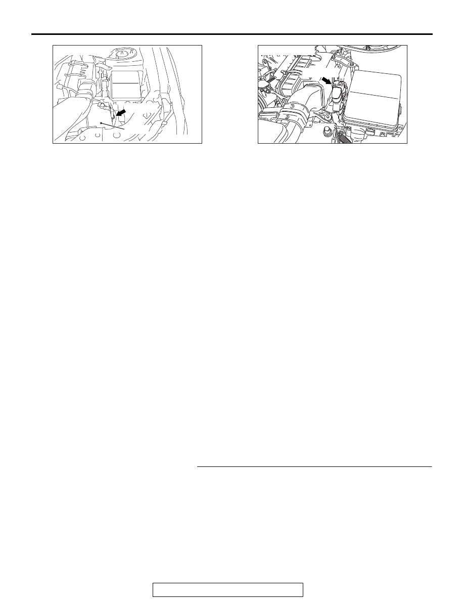
STEP 1. Check harness connector A-65 at battery current 
sensor for damage
Q: Is the harness connector in good condition?

YES : Go to Step 2.
NO :  Repair or replace it. Refer to GROUP 00E, Harness 

Connector Inspection 

P.00E-2

. Then go to Step 13.

AK900202 AF

A-65 (GR)

Connector: A-65

Battery

AK704097AB

Connector: B-11

B-11 (GR)

MULTIPORT FUEL INJECTION (MFI) DIAGNOSIS

TSB Revision

MULTIPORT FUEL INJECTION (MFI) <2.4L ENGINE>

13A-608

STEP 2. Check battery current sensor itself

• Check battery current sensor itself (Refer to GROUP 54A − 

Battery 

− Inspection − Battery Current Sensor Check <2.4 L 

Engine

P.54A-12

).

Q: Is the check result normal?

YES : Go to Step 3.
NO :  Replace the battery current sensor. Then go to Step 

13.

STEP 3. Measure the sensor supply voltage at battery 
current sensor harness side connector A-65.
(1) Disconnect the connector A-65 and measure at the harness 

side.

(2) Turn the ignition switch to the "ON" position.
(3) Measure the voltage between terminal No. 1 and ground.

• Voltage should be between 4.9 and 5.1 volts.

(4) Turn the ignition switch to the "LOCK" (OFF) position.
Q:  Is the measured voltage between 4.9 and 5.1 volts?

YES : Go to Step 7.
NO :  Go to Step 4.

STEP 4. Check harness connector B-11 at ECM for 
damage.
Q: Is the harness connector in good condition?

YES : Go to Step 5.
NO :  Repair or replace it. Refer to GROUP 00E, Harness 

Connector Inspection 

P.00E-2

. Then go to Step 13.

STEP 5. Check for open circuit and short circuit to ground 
between battery current sensor connector A-65 (terminal 
No. 1) and ECM connector B-11 (terminal No. 99).
Q: Is the harness wire in good condition?

YES : Go to Step 6.
NO :  Repair it. Then go to Step 13.

AKA00479

1

3

2

4

AC

A-65 harness 
connector: 
component side

MULTIPORT FUEL INJECTION (MFI) DIAGNOSIS

TSB Revision

MULTIPORT FUEL INJECTION (MFI) <2.4L ENGINE>

13A-609

STEP 6. Using scan tool MB991958, read the diagnostic 
trouble code (DTC).
(1) Connect scan tool MB991958 to the data link connector. 
(2) Turn the ignition switch to the "ON" position.
(3) After the DTC has been deleted, read the DTC again.
(4)  Turn the ignition switch to the "LOCK" (OFF) position.
Q: Is the DTC P1608 set?

YES : Replace the ECM. When the ECM is replaced, 

register the ID code. Refer to GROUP 42B, Diagnosis 
− ID Code Registration Judgment Table <Vehicles 

with KOS> 

P.42B-15

 or GROUP 42C, Diagnosis 

− ID 

Codes Registration Judgment Table <Vehicles with 
WCM> 

P.42C-10

. Then go to Step 13.

NO :  It can be assumed that this malfunction is intermittent. 

Refer to GROUP 00, How to Use 
Troubleshooting/Inspection Service Points 

− How to 

Cope with Intermittent Malfunctions 

P.00-15

.

STEP 7. Check the continuity at battery current sensor 
harness side connector A-65.
(1) Disconnect the connector A-65 and measure at the harness 

side.

(2) Check for the continuity between terminal No. 3 and 

ground.

• Continuity (2 ohms or less)

Q: Does continuity exist?

YES : Go to Step 10.
NO :  Go to Step 8.

STEP 8. Check harness connector B-11 at ECM for 
damage.
Q: Is the harness connector in good condition?

YES : Go to Step 9.
NO :  Repair or replace it. Refer to GROUP 00E, Harness 

Connector Inspection 

P.00E-2

. Then go to Step 13.

STEP 9. Check for open circuit and harness damage 
between battery current sensor connector A-65 (terminal 
No. 3) and ECM connector B-11 (terminal No. 101).
Q: Is the harness wire in good condition?

YES : Go to Step 6.
NO :  Repair it. Then go to Step 13.

AK700568AB

MB991824

MB991827

MB991910

Data link
connector

AKA00477

1

3

2

4

AC

A-65 harness 
connector: 
component side

MULTIPORT FUEL INJECTION (MFI) DIAGNOSIS

TSB Revision

MULTIPORT FUEL INJECTION (MFI) <2.4L ENGINE>

13A-610

STEP 10. Check harness connector B-11 at ECM for 
damage.
Q: Is the harness connector in good condition?

YES : Go to Step 11.
NO :  Repair or replace it. Refer to GROUP 00E, Harness 

Connector Inspection 

P.00E-2

. Then go to Step 13.

STEP 11. Check for harness damage between battery 
current sensor connector A-65 (terminal No. 1) and ECM 
connector B-11 (terminal No. 99).
Q: Is the harness wire in good condition?

YES : Go to Step 12.
NO :  Repair it. Then go to Step 13.

STEP 12. Check for open circuit, short circuit to ground 
and harness damage between battery current sensor 
connector A-65 (terminal No. 4) and ECM connector B-11 
(terminal No. 100).
Q: Is the harness wire in good condition?

YES : Go to Step 6.
NO :  Repair it. Then go to Step 13.

STEP 13. Using scan tool MB991958, read the diagnostic 
trouble code (DTC).
(1) Connect scan tool MB991958 to the data link connector. 
(2) Start the engine and run at idle.
(3) After the DTC has been deleted, read the DTC again.
(4) Turn the ignition switch to the "LOCK" (OFF) position.
Q: Is the DTC P1608 set?

YES : Retry the troubleshooting.
NO :  The inspection is complete.

AK700568AB

MB991824

MB991827

MB991910

Data link
connector


Content   ..  694  695  696  697   ..