Mitsubishi Outlander GS45X. Manual - part 689


  Index      Mitsubishi     Mitsubishi Outlander GS45X - service repair manual


Search            


Content   ..  687  688  689  690   ..


Mitsubishi Outlander GS45X. Manual - part 689


MULTIPORT FUEL INJECTION (MFI) DIAGNOSIS

TSB Revision

MULTIPORT FUEL INJECTION (MFI) <2.4L ENGINE>

13A-579

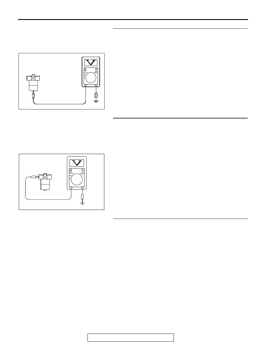
STEP 3. Measure the power supply voltage at throttle 
actuator control motor relay harness side connector A-21X
(1) Disconnect the connector A-21X and measure at the 

harness side.

(2) Measure the voltage between terminal No. 4 and ground.

• Voltage should be battery positive voltage.

Q: Is battery positive voltage (approximately 12 volts) 

present?
YES : 
Go to Step 4.
NO :  Repair it harness wire between battery and throttle 

actuator control motor relay connector A-21X 
(terminal No. 4) because of open circuit or short 
circuit to ground. Then go to Step 14.

STEP 4. Measure the power supply voltage at throttle 
actuator control motor relay harness side connector 
A-21X.
(1) Disconnect the connector A-21X and measure at the 

harness side.

(2) Turn the ignition switch to the "ON" position.
(3) Measure the voltage between terminal No. 2 and ground.

• Voltage should be battery positive voltage.

(4) Turn the ignition switch to the "LOCK" (OFF) position.
Q: Is battery positive voltage (approximately 12 volts) 

present?
YES : 
Go to Step 6.
NO :  Go to Step 5.

STEP 5. Check harness connector A-33X at MFI relay for 
damage.
Q: Is the harness connector in good condition?

YES : Repair harness wire between MFI relay connector 

A-33X (terminal No. 2) and throttle actuator control 
motor relay connector A-21X (terminal No. 2) 
because of open circuit or short circuit to ground. 
Then go to Step 14.

NO :  Repair or replace it. Refer to GROUP 00E, Harness 

Connector Inspection 

P.00E-2

. Then go to Step 14.

2

1

3
4

AK604215 AC

A-21X harness
connector:
component side

AK604216

2

1

3
4

AC

A-21X harness
connector:
component side 

MULTIPORT FUEL INJECTION (MFI) DIAGNOSIS

TSB Revision

MULTIPORT FUEL INJECTION (MFI) <2.4L ENGINE>

13A-580

STEP 6. Measure the power supply voltage at ECM harness 
side connector B-11.
(1) Disconnect the connector B-11 and measure at the harness 

side.

(2) Short-circuit the terminal No. 73 of the ECM harness 

connector to the ground.

(3) Measure the voltage between terminal No. 84 and ground.

• Voltage should be battery positive voltage.

Q: Is battery positive voltage (approximately 12 volts) 

present?
YES : 
Go to Step 7.
NO :  Repair harness wire between throttle actuator control 

motor relay connector A-21X (terminal No. 1) and 
ECM connector B-11 (terminal No. 84) because of 
open circuit or short circuit to ground. Then go to Step 
14.

82 81 80 79 78 77 76 75 74 73 72 71

94 93 92 91 90 89 88 87 86 85 84 83

99 98 97 96 95

100

101

102

103

104

105

106

112

113

114

109 108

107

110

111

115

116

117

118

AK604217 AC

B-11 harness
connector:
component side

MULTIPORT FUEL INJECTION (MFI) DIAGNOSIS

TSB Revision

MULTIPORT FUEL INJECTION (MFI) <2.4L ENGINE>

13A-581

STEP 7. Measure the power supply voltage at ECM harness 
side connector B-11.
(1) Disconnect the connector B-11 and measure at the harness 

side.

(2) Short-circuit the terminals No. 73 and No. 84 of the ECM 

harness connector to the ground.

(3) Measure the voltage between terminal No. 72 and ground.

• Voltage should be battery positive voltage.

Q: Is battery positive voltage (approximately 12 volts) 

present?
YES : 
Go to Step 10.
NO :  Go to Step 8.

STEP 8. Check for open circuit and short circuit to ground 
between throttle actuator control motor relay connector 
A-21X (terminal No. 3) and ECM connector B-11 (terminal 
No. 72).
Q: Is the harness wire in good condition?

YES : Go to Step 9.
NO :  Repair it. Then go to Step 14.

STEP 9. Check for harness damage between MFI relay 
connector A-33X (terminal No. 2) and throttle actuator 
control motor relay connector A-21X (terminal No. 2).
Q: Is the harness wire in good condition?

YES : Repair harness wire between throttle actuator control 

motor relay connector A-21X (terminal No. 1) and 
ECM connector B-11 (terminal No. 84) because of 
harness damage. Then go to Step 14.

NO :  Repair it. Then go to Step 14.

82 81 80 79 78 77 76 75 74 73 72 71

94 93 92 91 90 89 88 87 86 85 84 83

99 98 97 96 95

100

101

102

103

104

105

106

112

113

114

109 108

107

110

111

115

116

117

118

AK604218 AC

B-11 harness
connector:
component side

MULTIPORT FUEL INJECTION (MFI) DIAGNOSIS

TSB Revision

MULTIPORT FUEL INJECTION (MFI) <2.4L ENGINE>

13A-582

STEP 10. Check harness connector B-11 at ECM for 
damage.
Q:  Is the harness connector in good condition?

YES : Go to Step 11.
NO :  Repair or replace it. Refer to GROUP 00E, Harness 

Connector Inspection 

P.00E-2

. Then go to Step 14.

STEP 11. Check for harness damage between battery and 
throttle actuator control motor relay connector A-21X 
(terminal No. 4).
Q: Is the harness wire in good condition?

YES : Go to Step 12.
NO :  Repair it. Then go to Step 14.

STEP 12. Check for harness damage between throttle 
actuator control motor relay connector A-21X (terminal No. 
3) and ECM connector B-11 (terminal No. 72).
Q: Is the harness wire in good condition?

YES : Go to Step 13.
NO :  Repair it. Then go to Step 14.

STEP 13. Using scan tool MB991958, read the diagnostic 
trouble code (DTC).

CAUTION

To prevent damage to scan tool MB991958, always turn the 
ignition switch to the "LOCK" (OFF) position before con-
necting or disconnecting scan tool MB991958.
(1) Connect scan tool MB991958 to the data link connector.
(2) Turn the ignition switch to the "ON" position.
(3) After the DTC has been deleted, read the DTC again.
(4) Turn the ignition switch to the "LOCK" (OFF) position.
Q: Is DTC P0657 set?

YES : Replace the ECM. When the ECM is replaced, 

register the ID code. Refer to GROUP 42B, Diagnosis 
− ID Code Registration Judgment Table <Vehicles 

with KOS> 

P.42B-15

 or GROUP 42C, Diagnosis 

− ID 

Codes Registration Judgment Table <Vehicles with 
WCM> 

P.42C-10

. Then go to Step 14.

NO :  It can be assumed that this malfunction is intermittent. 

Refer to GROUP 00, How to Use 
Troubleshooting/Inspection Service Points 

− How to 

Cope with Intermittent Malfunctions 

P.00-15

.

AK700568AB

MB991824

MB991827

MB991910

Data link
connector


Content   ..  687  688  689  690   ..