Mitsubishi Outlander GS45X. Manual - part 623
MULTIPORT FUEL INJECTION (MFI) DIAGNOSIS
TSB Revision
MULTIPORT FUEL INJECTION (MFI) <2.4L ENGINE>
13A-315
DTC SET CONDITIONS <Circuit continuity
− shorted high>
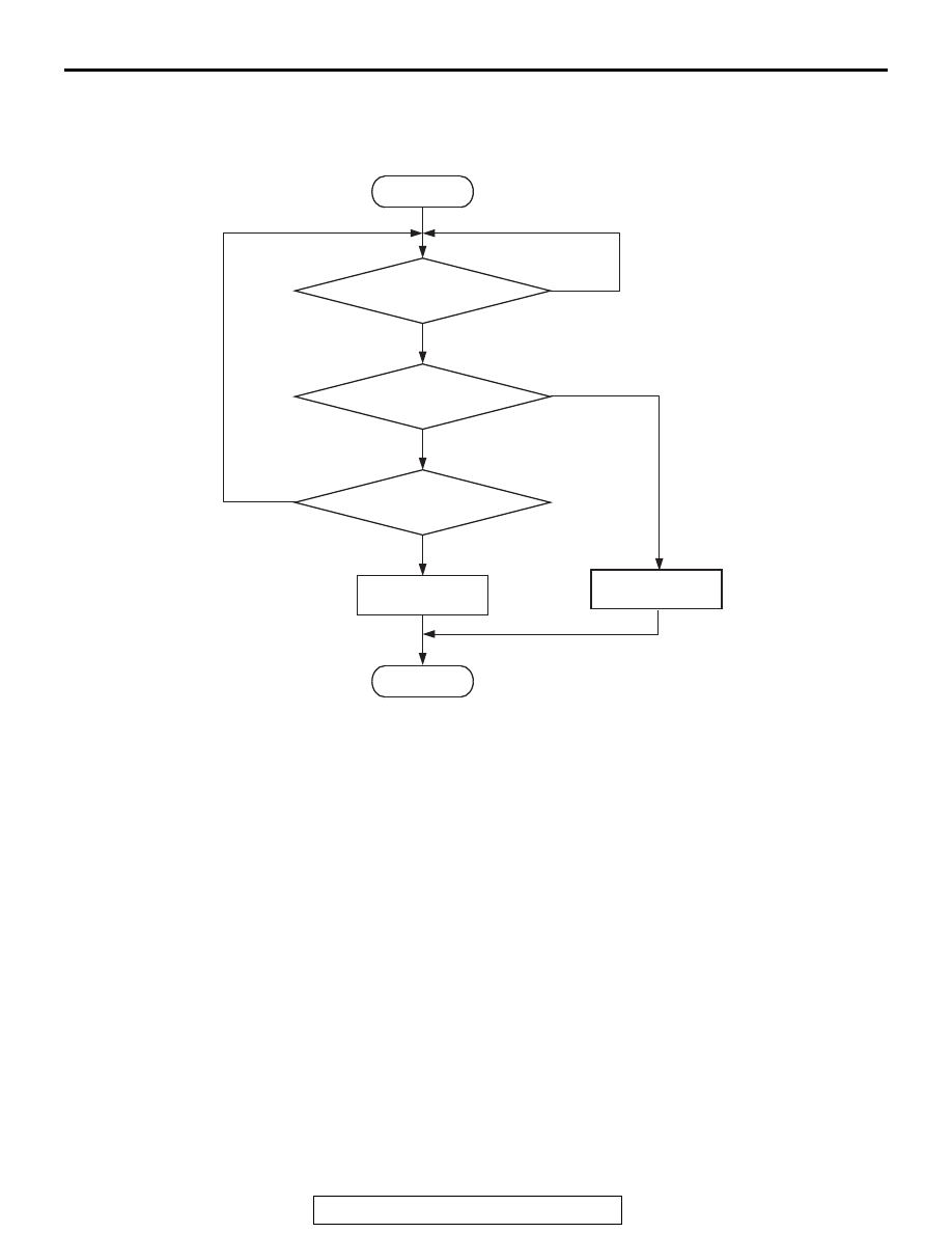
Logic Flow Chart
Check Condition
• Engine is running.
Judgement Criterion
• The coil current is 4.5 amperes or more with the
injector driving for 2 seconds.
.
OBD-II DRIVE CYCLE PATTERN
Refer to Diagnostic Function
− OBD-II Drive Cycle −
Pattern 23
.
TROUBLESHOOTING HINTS (The most
likely causes for this code to be set are:)
• No. 3 cylinder injector failed.
• Open or shorted No. 3 cylinder injector circuit,
harness damage, or connector damage.
• ECM failed.
DIAGNOSIS
Required Special Tools:
• MB991958: Scan Tool (M.U.T.-III Sub Assembly)
• MB991824: V.C.I.
• MB991827: USB Cable
• MB991910: Main Harness A
• MB991658: Test Harness
• MB992110: Power Plant ECU Check Harness
Good
Malfunction
Current >= 4.5A
End
Yes
No
No
No
AK604332
Start
Yes
Yes
Continuous
failure for 2secs
Monitoring
condition