Mitsubishi Outlander GS45X. Manual - part 600


  Index      Mitsubishi     Mitsubishi Outlander GS45X - service repair manual


Search            


Content   ..  598  599  600  601   ..


Mitsubishi Outlander GS45X. Manual - part 600


MULTIPORT FUEL INJECTION (MFI) DIAGNOSIS

TSB Revision

MULTIPORT FUEL INJECTION (MFI) <2.4L ENGINE>

13A-223

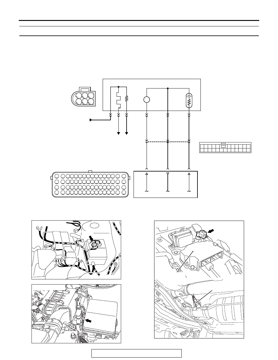
DTC P0131: Linear Air-Fuel Ratio Sensor Circuit Low Voltage

1

2

3 4 5 6 7 8 9 10 11 12 13 14 15 16

17 18 19 20 21 22 23 24 25 26 27 28 29 30 31 32

33 34 35 36 37 38 39 40 41 42 43 44 45 46 47 48

49 50 51 52 53 54 55 56 57 58 59 60 61 62 63 64

P

3

2

1

6

5

4

AKA00449

1

12 13 14 15 16 1718 19 20 2122 2324

2 3 4 5

6 7 8 9 10 11

LINEAR AIR-FUEL RATIO SENSOR CIRCUIT

LINEAR 
AIR-FUEL 
RATIO 
SENSOR

FROM 
MFI RELAY

WHITE

BLA

CK

RED

WHITE

BLA

CK

RED

C-142

ENGINE
CONTROL
MODULE

38

39

56

4

5

1

14

20

21

2

6

3

B-10

A-12

AC

TO ECM TO ECM

AKA00842 AB

Connector: A-12

A-12

AK704090AB

Connector: B-10

B-10 (GR)

AK704089AD

Linear air-fuel
ratio sensor

SRS-ECU

Connector: C-142

C-142 (B)

MULTIPORT FUEL INJECTION (MFI) DIAGNOSIS

TSB Revision

MULTIPORT FUEL INJECTION (MFI) <2.4L ENGINE>

13A-224

.

CIRCUIT OPERATION

The linear air-fuel ratio sensor and the ECM are con-
nected by the following three lines to detect the 
air-fuel ratio.

• The line between the linear air-fuel ratio sensor 

(terminal No. 1) and the ECM (terminal No. 56) 
detects the air-fuel ratio.

• The auxiliary line between the linear air-fuel ratio 

sensor (terminal No. 4) and the ECM (terminal 
No. 38) detects the air-fuel ratio.

• The line between the linear air-fuel ratio sensor 

(terminal No. 5) and the ECM (terminal No. 39) is 
connected to ground.

.

TECHNICAL DESCRIPTION

• The ECM effects air/fuel ratio feedback control in 

accordance with the signals from the linear 
air-fuel ratio sensor.

• If the linear air-fuel ratio sensor has deteriorated, 

corrections will be made by the heated oxygen 
sensor (rear).

.

DESCRIPTIONS OF MONITOR METHODS

• If one of the three line voltages is excessively low 

or if all the three line voltages are excessively 
low, the DTC is stored as a malfunction.

.

MONITOR EXECUTION

Continuous

.

MONITOR EXECUTION CONDITIONS 
(Other monitor and Sensor)

Other Monitor (There is no temporary DTC stored 

in memory for the item monitored below)

• Linear air-fuel ratio sensor heater monitor

• Misfire monitor

• Fuel system monitor

Sensor (The sensor below is determined to be 

normal)

• Mass airflow sensor

• Engine coolant temperature sensor

• Intake air temperature sensor

• Barometric pressure sensor

• Throttle position sensor

• Accelerator pedal position sensor

.

MULTIPORT FUEL INJECTION (MFI) DIAGNOSIS

TSB Revision

MULTIPORT FUEL INJECTION (MFI) <2.4L ENGINE>

13A-225

DTC SET CONDITIONS
Logic Flow Chart

.

Check Conditions

• Battery positive voltage is between 10 and 16.5 

volts.

• More than 40 seconds have passed since the 

engine starting sequence was completed.

Judgement Criterion

• The pumping circuit voltage is be lower than 2 

volts for 2 seconds.

or

• The reference circuit voltage is be lower than 1.2 

volt for 2 seconds.

or

• The negative circuit voltage is be lower than 1.2 

volt for 2 seconds.

.

OBD-II DRIVE CYCLE PATTERN

• Refer to Diagnosis Function − OBD-II Drive Cycle 

− Pattern 22 

P.13A-11

.

.

TROUBLESHOOTING HINTS (The most 
likely causes for this code to be set are:)

• Linear air-fuel ratio sensor failed.

• Shorted linear air-fuel ratio sensor circuit, or con-

nector damage.

• ECM failed.

End

Malfunction

No

No

No

2secs have passed?

Pumping circuit voltage < 2.0 V 

or 

Reference circuit voltage < 1.2 V 

or 

Negative circuit voltage < 1.2 V

Good

AK900357

Start

Yes

Yes

Yes

Monitoring
conditions

MULTIPORT FUEL INJECTION (MFI) DIAGNOSIS

TSB Revision

MULTIPORT FUEL INJECTION (MFI) <2.4L ENGINE>

13A-226

DIAGNOSIS

Required Special Tools:

• MB991958: Scan Tool (M.U.T.-III Sub Assembly)

• MB991824: V.C.I.

• MB991827: USB Cable

• MB991910: Main Harness A

STEP 1. Check harness connector C-142 at linear air-fuel 
ratio sensor and harness connector B-10 at ECM for 
damage.
Q: Is the harness connector in good condition?

YES : Go to Step 2.
NO :  Repair or replace it. Refer to GROUP 00E, Harness 

Connector Inspection 

P.00E-2

. Then go to Step 7.

STEP 2. Check for short circuit to ground between linear 
air-fuel ratio sensor connector C-142 (terminal No. 4) and 
ECM connector B-10 (terminal No. 38).
NOTE: Check harness after checking intermediate connector 
A-12. If intermediate connector is damaged, repair or replace it. 
Refer to GROUP 00E, Harness Connector Inspection 

P.00E-2

Then go to Step 7.
Q: Is the harness wire in good condition?

YES : Go to Step 3.
NO :  Repair it. Then go to Step 7.

STEP 3. Check for short circuit to ground between linear 
air-fuel ratio sensor connector C-142 (terminal No. 1) and 
ECM connector B-10 (terminal No. 56).
NOTE: Check harness after checking intermediate connector 
A-12. If intermediate connector is damaged, repair or replace it. 
Refer to GROUP 00E, Harness Connector Inspection 

P.00E-2

Then go to Step 7.
Q: Is the harness wire in good condition?

YES : Go to Step 4.
NO :  Repair it. Then go to Step 7.

STEP 4. Check for short circuit to ground between linear 
air-fuel ratio sensor connector C-142 (terminal No. 5) and 
ECM connector B-10 (terminal No. 39).
NOTE: Check harness after checking intermediate connector 
A-12. If intermediate connector is damaged, repair or replace it. 
Refer to GROUP 00E, Harness Connector Inspection 

P.00E-2

Then go to Step 7.
Q: Is the harness wire in good condition?

YES : Go to Step 5.
NO :  Repair it. Then go to Step 7.


Content   ..  598  599  600  601   ..