Mitsubishi Outlander GS45X. Manual - part 546
SERVICE SPECIFICATIONS
TSB Revision
MULTIPORT FUEL INJECTION (MFI) <2.4L ENGINE>
13A-7
SERVICE SPECIFICATIONS
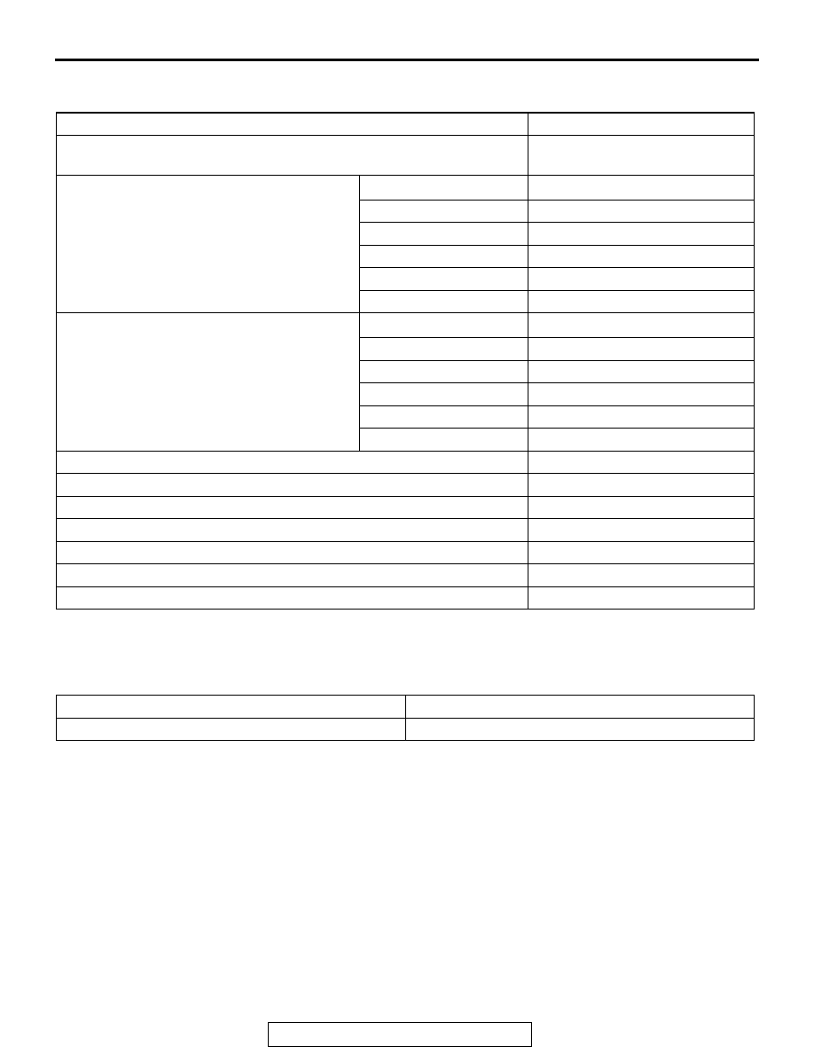
M1131000303113
SEALANT AND ADHESIVE
M1131000501456
ITEMS
STANDARD VALUE
Fuel pressure kPa (psi)
Approximately 324 (47) at curb
idle
Intake air temperature sensor resistance k
Ω −20°C (−4°F)
13
− 17
0
°C (32°F)
5.3
− 6.7
20
°C (68°F)
2.3
− 3.0
40
°C (104°F)
1.0
− 1.5
60
°C (140°F)
0.56
− 0.76
80
°C (176°F)
0.30
− 0.45
Engine coolant temperature sensor
resistance k
Ω
−20°C (−4°F)
14
− 17
0
°C (32°F)
5.1
− 6.5
20
°C (68°F)
2.1
− 2.7
40
°C (104°F)
0.9
− 1.3
60
°C (140°F)
0.48
− 0.68
80
°C (176°F)
0.26
− 0.36
Heated oxygen sensor output voltage V
0.6
− 1.0
Linear air-fuel ratio sensor heater resistance
Ω
2.3
− 4.2 [at 20°C (68°F)]
Heated oxygen sensor heater resistance
Ω
4.5
− 8.0 [at 20°C (68°F)]
Injector coil resistance
Ω
10.5
− 13.5 [at 20°C (68°F)]
Throttle actuator control motor coil resistance
Ω
0.3
− 80 [at 20°C (68°F)]
Intake engine oil control valve coil resistance
Ω
6.9
− 7.9 [at 20°C (68°F)]
Exhaust engine oil control valve coil resistance
Ω
6.9
− 7.9 [at 20°C (68°F)]
ITEM
SPECIFIED SEALANT
Engine coolant temperature sensor threaded portion LOCTITE 262 or equivalent