Mitsubishi Outlander GS45X. Manual - part 404
DIAGNOSIS
TSB Revision
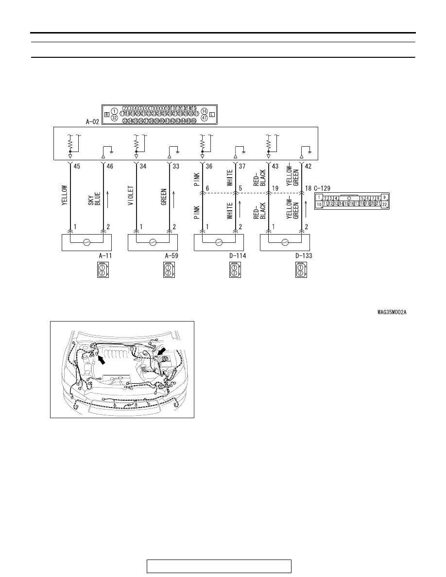
ACTIVE STABILITY CONTROL SYSTEM (ASC)
35C-43
DTC C1011: Abnormality in FL wheel speed sensor signal
Wheel Speed Sensor Circuit
ASC-ECU
FRONT
WHEEL
SPEED
SENSOR
(LH)
FRONT
WHEEL
SPEED
SENSOR
(RH)
REAR
WHEEL
SPEED
SENSOR
(LH)
REAR
WHEEL
SPEED
SENSOR
(RH)
AC901112
Connectors: A-02, A-11
A-02 (B)
AN
A-11 (B)