Mitsubishi Outlander GS45X. Manual - part 367


  Index      Mitsubishi     Mitsubishi Outlander GS45X - service repair manual


Search            


Content   ..  365  366  367  368   ..


Mitsubishi Outlander GS45X. Manual - part 367


ABS DIAGNOSIS

TSB Revision

ANTI-LOCK BRAKING SYSTEM (ABS)

35B-89

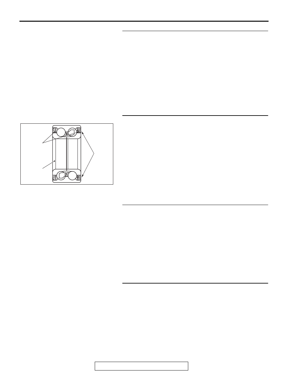
STEP 9. Check for wheel bearing looseness
NOTE: 

.

Loose wheel bearing may increase the gap between the 
wheel speed sensor <FL> and the wheel speed detection 
magnet encoder.

Check the wheel bearing <FL> for looseness (Refer to 
GROUP 26 

 Wheel Bearing Play Check 

P.26-11

).

Q: Is the check result normal?

YES : Go to Step 10.
NO :  Replace the wheel bearing <FL> (Refer to GROUP 26 

− Front Axle Hub Assembly 

P.26-13

). Then go to Step 

13.

STEP 10. Check wheel speed detection encoder
Check the encoder for adhesion of foreign materials or defor-
mation.
Q: Is the check result normal?

YES : Go to Step 11.
NO (Adhesion of foreign materials) : Remove the foreign 

materials and clean the encoder so as not to disturb 
the magnetization pattern on it while taking care of the 
magnet, magnetic substance, and magnetic 
attraction. Then go to Step 13.

NO (Deformation) : Replace the wheel bearing <FL> 

(Refer to GROUP 26 

− Front Axle Hub Assembly 

P.26-13

). Then go to Step 13.

STEP 11. Check whether the DTC is reset.
(1) Erase the DTC.
(2) Drive the vehicle at 12mph (20 km/h) or higher.

NOTE: The ABS warning light does not turn OFF in some 
cases unless the vehicle runs at 12mph (20 km/h) or higher.

Q: Is DTC C1046 set?

YES : Replace the wheel speed sensor <FL> (Refer to 

P.35B-189

). Then go to Step 12.

NO :  Intermittent malfunction (Refer to GROUP 00 

− How 

to Use Troubleshooting/How to Cope with Intermittent 
Malfunctions 

P.00-15

).

STEP 12. Check whether the DTC is reset.
(1) Erase the DTC.
(2) Drive the vehicle at 12mph (20 km/h) or higher.

NOTE: The ABS warning light does not turn OFF in some 
cases unless the vehicle runs at 12mph (20 km/h) or higher.

Q: Is DTC C1046 set?

YES : Replace the hydraulic unit (integrated with ABS-ECU) 

(Refer to 

P.35B-188

). Then go to Step 13.

NO :  The procedure is complete.

AC608761

Oil seal

Magnetic
encoder

Wheel
bearing

AB

ABS DIAGNOSIS

TSB Revision

ANTI-LOCK BRAKING SYSTEM (ABS)

35B-90

STEP 13. Check whether the DTC is reset.
(1) Erase the DTC.
(2) Drive the vehicle at 12mph (20 km/h) or higher.

NOTE: The ABS warning light does not turn OFF in some 
cases unless the vehicle runs at 12mph (20 km/h) or higher.

Q: Is DTC C1046 set?

YES : Return to Step 1.
NO :  The procedure is complete.

DTC C1047: FR wheel speed sensor control phase time exceeded

AC703729

Wheel Speed Sensor Circuit

ABS-ECU

(LH)

(LH)

(RH)

(RH)

REAR WHEEL SPEED SENSOR

AB

FRONT WHEEL SEED SENSOR

AC901112

Connectors: A-01, A-59

A-01 (B)

AL

A-59 (B)

ABS DIAGNOSIS

TSB Revision

ANTI-LOCK BRAKING SYSTEM (ABS)

35B-91

CAUTION

If there is any problem in the CAN bus lines, an incorrect 
DTC may be set. Prior to this diagnosis, diagnose the CAN 
bus lines (Refer to GROUP 54C 

 CAN Bus Line Diagnostic 

Flow 

P.54C-10

).

.

CIRCUIT OPERATION

• The wheel speed sensor is a type of pulse generator. It con-

sists of encoders (a plate on which north and south pole 
sides of the magnets are arranged alternately) for detecting 
the wheel speed which rotates at the same speed of the 
wheels and wheel speed sensors. This sensor outputs fre-
quency pulse signals in proportion to the wheel speed.

• The pulse signals, which the wheel speed sensor creates, 

are sent to ABS-ECU. ABS-ECU uses the frequency of the 
pulse signals to determine the wheel speed.

.

DTC SET CONDITIONS

This DTC is set if any malfunction below is found:

• When the brake fluid pressure is decreased for a long time.

• When the brake fluid pressure is held for a long time.

.

PROBABLE CAUSES

• Damaged wiring harness and connectors

• External noise interference

• Malfunction of wheel speed sensor

• ABS-ECU malfunction

• Excessive gap between the wheel speed sensor and the 

wheel speed detection encoder

• Adhesion of foreign materials on the wheel speed sensor

• Adhesion of foreign materials on the wheel speed detection 

encoder

• Wheel bearing malfunction

• Improper installation of the wheel speed sensor

• Deformation of the wheel speed detection encoder

• Disturbance of magnetization pattern for wheel speed 

detection encoder

• Missing teeth of the wheel speed detection encoder

DIAGNOSIS

Required Special Tools:

• MB991958: Scan Tool (M.U.T.-III Sub Assembly)

• MB991824: Vehicle Communication Interface (V.C.I.)

• MB991827: M.U.T.-III USB Cable

• MB991910: M.U.T.-III Main Harness A

ABS DIAGNOSIS

TSB Revision

ANTI-LOCK BRAKING SYSTEM (ABS)

35B-92

STEP 1. Using scan tool MB991958, diagnose the CAN bus 
lines.
Use scan tool to diagnose the CAN bus lines.
Q: Is the check result normal?

YES : Go to Step 3.
NO :  Repair the CAN bus lines (Refer to GROUP 54C 

− 

CAN Bus Diagnostics Table 

P.54C-17

). On 

completion, go to Step 2.

STEP 2. DTC recheck after resetting CAN bus lines
Q: Is DTC C1047 set?

YES : Go to Step 3.
NO :  The procedure is complete.

STEP 3. Using scan tool MB991958, check the DTC
Check that the DTCs C1015, C101C, C101F, or C1042 are also 
set.
Q: Are DTC C1015, C101C, C101F, or C1042 also set?

YES : Carry out the diagnosis for the relevant DTCs.
NO :  Go to Step 4.

STEP 4. Using scan tool MB991958, check the data list
Check the following data list (Refer to 

P.35B-179

).

• Item No.02: FR wheel speed sensor

Q: Is the check result normal?

YES : Go to Step 11.
NO :  Go to Step 5.

STEP 5. Connector check: A-01 ABS-ECU connector, A-59 
front wheel speed sensor <RH> connector
Q: Is the check result normal?

YES : Go to Step 6.
NO :  Repair the defective connector. Then go to Step 13.

STEP 6. Wiring harness check between A-01 ABS-ECU 
connector terminal No.22 and A-59 front wheel speed 
sensor <RH> connector terminal No.1, and between A-01 
ABS-ECU connector terminal No.21 and A-59 front wheel 
speed sensor <RH> connector terminal No.2.
Q: Is the check result normal?

YES : Go to Step 7.
NO :  Repair the wiring harness. Then go to Step 13.


Content   ..  365  366  367  368   ..