Mitsubishi Outlander GS45X. Manual - part 217


  Index      Mitsubishi     Mitsubishi Outlander GS45X - service repair manual


Search            


Content   ..  215  216  217  218   ..


Mitsubishi Outlander GS45X. Manual - part 217


THEFT ALARM

TSB Revision

CHASSIS ELECTRICAL

54A-865

.

TECHNICAL DESCRIPTION (COMMENT)

If horns do not sound, the horn input signal circuit or 
the ETACS-ECU may be defective.

.

TROUBLESHOOTING HINTS

• Horns may be defective

• Horn relay may be defective

• The ETACS-ECU may be defective

• The wiring harness or connectors may have 

loose, corroded, or damaged terminals, or termi-
nals pushed back in the connector

DIAGNOSIS

Required Special Tools:

• MB992006: Extra fine probe

• MB991223: Harness set

• MB991958: Scan Tool (M.U.T.-III Sub Assembly)

• MB991824: Vehicles Communication Interface (V.C.I.)

• MB991827: M.U.T.-III USB Cable

• MB991910: M.U.T.-III Main Harness A (Vehicles with 

CAN communication system)
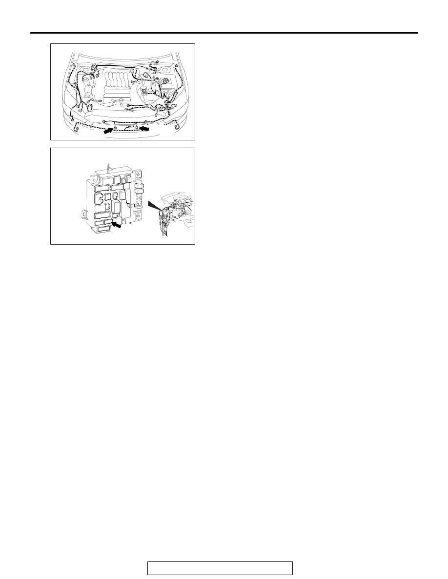
AC901112

Connectors: A-45, A-49

A-49 (B)

AJ

A-45 (B)

ACA02655AW

Connector: C-312

THEFT ALARM

TSB Revision

CHASSIS ELECTRICAL

54A-866

STEP 1. Using scan tool MB991958, read the diagnostic 
trouble code. 
Check if DTC is set to the ETACS-ECU.

CAUTION

To prevent damage to scan tool MB991958, always turn the 
ignition switch to the "LOCK" (OFF) position before con-
necting or disconnecting scan tool MB991958.
(1) Connect scan tool MB991958. Refer to "How to connect 

scan too (M.U.T.-III) 

P.54A-839

."

(2) Turn the ignition switch to the "ON" position.
(3) Check whether the ETACS-ECU related DTC is set.
(4) Turn the ignition switch to the "LOCK" (OFF) position.
Q: Is the DTC set?

YES : Diagnose the ETACS-ECU. Refer to 

P.54A-733

.

NO :  Go to Step 2.

STEP 2. Check which horn is defective.
Check which horn does not sound when the theft-alarm system 
is triggered.
Q: Which horn does not sound?

 Horn (HI) and horn (LO) : Go to Step 3.
Horn (HI) only : Go to Step 9.
Horn (LO) only : Go to Step 12.

STEP 3. Check horn relay connector A-15X for loose, 
corroded or damaged terminals, or terminals pushed back 
in the connector.
Q: Is horn relay connector A-15X in good condition?

YES : Go to Step 4.
NO :  Repair the damaged parts.

STEP 4. Check the horn relay.
Refer to 

P.54A-879

.

Q: Is the horn relay in good condition

YES : Go to Step 5.
NO :  Replace the horn relay.

ZC501967

AC404789

AC702802

MB991824

MB991827

MB991910

Data link

connector

AB

THEFT ALARM

TSB Revision

CHASSIS ELECTRICAL

54A-867

STEP 5. Measure the voltage at horn relay A-15X.
(1) Remove the relay, and measure at the relay box side.
(2) Measure the voltage between horn relay connector A-15X 

(terminal No. 2, 4) and the body ground.

• The voltage should measure approximately 12 volts 

(battery positive voltage).

Q: Is the measured voltage approximately 12 volts (battery 

positive voltage)?
YES : 
Go to Step 7.
NO :  Go to Step 6.

STEP 6. Check the Wiring harness between horn relay 
connector A-15X (terminal No. 2,4) and fusible link (36).
Check the power supply lines for open circuit and short circuit.
Q: Is the check result normal?

YES : The trouble can be an intermittent malfunction (Refer 

to GROUP 00, How to use 
Troubleshooting/inspection Service Points 

− How to 

Cope with Intermittent Malfunction 

P.00-15

).

NO :  Repair the wiring harness between theft-alarm horn 

relay connector A-15X and fusible link (36).

STEP 7. Check ETACS-ECU connector C-312 for loose, 
corroded or damaged terminals, or terminals pushed back 
in the connector.
Q: Is ETACS-ECU connector C-312 in good condition?

YES : Go to Step 8.
NO :  Repair the damaged parts.

STEP 8. Check the Wiring harness between horn relay 
connector A-15X (terminal No. 1) and ETACS-ECU 
connector C-312 (terminal No. 11).
Check the output line for open circuit and short circuit.
Q: Is the check result normal?

YES : Go to Step 9.
NO :  Repair the wiring harness between horn relay 

connector A-15X and ETACS-ECU connector C-312.

STEP 9. Check horn (HI) connector A-49 for loose, 
corroded or damaged terminals, or terminals pushed back 
in the connector.
Q: Is horn (HI) connector A-49 in good condition?

YES : Go to Step 10.
NO :  Repair the damaged parts.

AC702831AQ

Relay box side: A-15X

THEFT ALARM

TSB Revision

CHASSIS ELECTRICAL

54A-868

STEP 10. Check the Wiring harness between horn (HI) 
connector A-49 (terminal No. 1) and horn relay connector 
A-15X (terminal No. 3).
Check the output line for open circuit and short circuit.
Q: Is the check result normal?

YES : Go to Step 11.
NO :  Repair the wiring harness between horn (HI) 

connector A-49 and horn relay connector A-15X.

STEP 11. Check the horn (HI) work normally.
Connect the battery as shown, and verify that the horn sounds.
Q: Does horn (HI) work normally?

YES : Go to Step 12.
NO :  Replace the horn (HI). Then, go to Step 12.

STEP 12. Check which horn is defective.
Check which horn does not sound when the theft-alarm system 
is triggered.
Q: Which horn does not sound?

 Horn (HI) and horn (LO) : Go to Step 13.
Horn (HI) only : Replace the ETACS-ECU.
Horn (LO) only : Go to Step 13.

STEP 13. Check horn (LO) connector A-45 for loose, 
corroded or damaged terminals, or terminals pushed back 
in the connector.
Q: Is horn (LO) connector A-45 in good condition?

YES : Go to Step 14.
NO :  Repair the damaged parts.

STEP 14. Check the Wiring harness between horn (LO) 
connector A-45 (terminal No. 1) and horn relay connector 
A-15X (terminal No. 3).
Check the output line for open circuit and short circuit.
Q: Is the check result normal?

YES : Go to Step 15.
NO :  Repair the wiring harness between horn (LO) 

connector A-45 and horn relay connector A-15X.

AC607630AC


Content   ..  215  216  217  218   ..