Mitsubishi Outlander GS45X. Manual - part 1642


  Index      Mitsubishi     Mitsubishi Outlander GS45X - service repair manual


Search            


Content   ..  1640  1641  1642  1643   ..


Mitsubishi Outlander GS45X. Manual - part 1642


DIAGNOSIS

TSB Revision

CVT

23A-125

Inspection Procedure 7: The fluid temperature warning lamp illuminates too frequently.

.

PROBABLE CAUSES

• Thermal deterioration of the transmission fluid

• Damaged wiring harness and connectors

• Malfunction of the transmission fluid temperature 

sensor

• Clogged coolant system

• Clogged air-cooled transmission fluid cooler sys-

tem

• Malfunction of the thermo valve

• Malfunction of TCM

• Malfunction of CVT assembly

DIAGNOSTIC PROCEDURE

STEP 1. Scan tool MB991958 special function
Check the deterioration level of the transmission fluid.
NOTE: The transmission fluid deterioration level is the accumu-
lation of the values counted depending on the fluid temperature 
of a certain period of time, and it shows the thermal deteriora-
tion level of the transmission fluid.
Q: Is the deterioration level of the transmission fluid less 

than 210,000?
YES : 
Go to Step 2.
NO :  Replace the transmission fluid.

STEP 2. M.U.T.-III data list
Item 5: Transmission fluid temperature sensor (Refer to Data 
List Reference Table 

P.23A-127

)

Q: Is the check result normal?

YES : Go to Step 3.
NO  :  Diagnostic trouble code No.P0710: Diagnose the 

transmission fluid temperature sensor 

P.23A-44

.

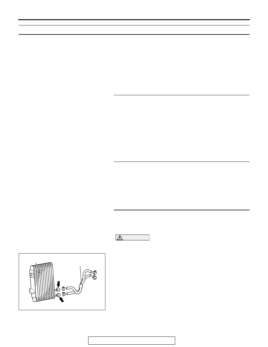
STEP 3. Air-cooled transmission fluid cooler system 
clogging check
Check if the air-cooled transmission fluid cooler system is 
clogged according to the following procedure.

CAUTION

Do not reuse the drained transmission fluid.
(1) Remove the transmission fluid cooler hose assembly.
(2) Blow air into the transmission fluid cooler hose assembly, 

and check that the air comes out from the opposite side.

(3) Blow air into the air-cooled transmission fluid cooler (A in 

the figure), and check that the air comes out from the 
opposite side (B in the figure).

(4) Install the parts, and replenish the transmission fluid to the 

specified quantity.

Q: Is the check result normal?

YES : Go to Step 4.
NO :  Replace the part(s) having damage or other 

problems.

AC711437AD

Air-cooled transmission
fluid cooler

Transmission fluid
cooler hose assembly

A

B

DIAGNOSIS

TSB Revision

CVT

23A-126

STEP 4. Thermo valve check
Refer to 

P.23A-167

.

Q: Is the check result normal?

YES : Go to Step 5.
NO :  Replace the thermo valve.

STEP 5. Coolant system clogging check
Check if the coolant system is clogged according to the follow-
ing procedure.

CAUTION

Do not reuse the drained coolant.
(1) Drain the coolant.
(2) Remove water feed hose A, water feed hose B and water 

return hose A.

(3) Blow air into the removed parts, and check that the air 

comes out from the opposite side.

(4) Blow air into the coolant outlet (A in the figure), and check 

that the air comes out from the opposite side (B in the 
figure).

(5) Install the parts, and replenish the coolant to the specified 

quantity.

Q: Is the check result normal?

YES : Go to Step 6.
NO :  Replace the part(s) having damage or other 

problems.

STEP 6. Retest the system.
Q: Does a malfunction take place again?

YES : Replace the CVT assembly.
NO :  Intermittent malfunction

AC711438AB

Water feed hose B

Water feed hose A

Water return hose A

A

B

DIAGNOSIS

TSB Revision

CVT

23A-127

DATA LIST REFERENCE TABLE

M1231208100687

Item 
No.

Display on scan 
tool

Check conditions

Normal conditions

1

Primary speed 
sensor signal

Driving conditions

Nearly the same as 
the tachometer 
display

2

Secondary speed 
sensor signal

Driving conditions

Nearly the same as 
the speedometer 
display

3

Primary pressure 
sensor signal

Always

0 V

4

Secondary pressure 
sensor signal

• Engine: Idling

• Transmission range: N

0.5 

− 3.0 V

5

Transmission fluid 
temperature sensor 
signal

Ignition switch: ON

Transmission fluid 
temperature: Approximately 
20

°C (68°F)

1.9 

− 2.2 V

Transmission fluid 
temperature: Approximately 
80

°C (176°F)

0.8 

− 1.1 V

6

Power supply 
voltage

Ignition switch: ON

Battery positive 
voltage

7

Primary speed

Driving conditions

Nearly the same as 
the tachometer 
display

8

Secondary speed

Driving conditions

Approximately 
(Speedometer 
display) 

× 45

9

Engine revolution

Engine: Idling

Nearly the same as 
the tachometer 
display

11

Real variable speed 
ratio

Driving conditions

2.34 

− 0.39

13

Accelerator position Accelerator pedal: Fully closed

0%

Accelerator pedal: Depressed

Opening angle value 
increases in 
response to the 
depression amount 
of the accelerator 
pedal.

Accelerator pedal: Fully opened

100%

18

Primary pressure

Always

0 MPa

19

Secondary pressure

• Engine: Idling

• Transmission range: N

0.1 

− 3.0 MPa  

(14.5 

− 435 psi)

DIAGNOSIS

TSB Revision

CVT

23A-128

20

Transmission fluid 
temperature

*

Ignition switch: ON

Transmission fluid 
temperature: Approximately 
20

°C (68°F)

39 

− 55 count

Transmission fluid 
temperature: Approximately 
80

°C (176°F)

152 

− 170 count

21

Vehicle speed 
(inference)

Driving conditions

Nearly the same as 
the speedometer 
display

22

Real vehicle speed

Driving conditions

Nearly the same as 
the speedometer 
display

26

Real step

Driving conditions

−20 to 190 step

30

LU solenoid monitor 
current

From lockup release to engage

− 0.7 A

31

LU solenoid output 
current

From lockup release to engage

− 0.7 A

32

Line pressure SOL. 
monitor current

• Engine: Idling

• Transmission range: N

0.45 

− 0.75 A

Engine: Stalled

0.08 

− 0.3 A

33

Line pressure SOL. 
output current

From low line pressure to high line pressure

− 0.8 A

34

Secondary PRS. 
SOL. monitor current

• Engine: Idling

• Transmission range: N

0.45 

− 0.75 A

Engine: Stalled

0.08 

− 0.3 A

35

Secondary PRS. 
SOL. monitor output 
current

From low secondary pressure to high secondary 
pressure

− 0.8 A

36

LU/SEL changeover 
SOL. output

Ignition switch: ON

Transmission range: P, N

ON

Transmission range: 5 or 
more seconds have passed 
after the selector lever has 
been moved to R or D 
position.

OFF

37

LU/SEL changeover 
SOL. monitor

Ignition switch: ON

Transmission range: P, N

ON

Transmission range: 5 or 
more seconds have passed 
after the selector lever has 
been moved to R or D 
position.

OFF

38

Stepper motor coil A Driving conditions

ON/OFF switches 
alternately.

39

Stepper motor coil B Driving conditions

ON/OFF switches 
alternately.

Item 
No.

Display on scan 
tool

Check conditions

Normal conditions


Content   ..  1640  1641  1642  1643   ..