Mitsubishi Outlander GS45X. Manual - part 1599


  Index      Mitsubishi     Mitsubishi Outlander GS45X - service repair manual


Search            


Content   ..  1597  1598  1599  1600   ..


Mitsubishi Outlander GS45X. Manual - part 1599


CRUISE CONTROL

TSB Revision

ENGINE AND EMISSION CONTROL

17-45

Inspection Procedure 3: When the "CANCEL" Switch is Set to ON, Cruise Control System is not 
Cancelled.

.

COMMENT

The cause is probably an open-circuit in the output 
circuit inside the "CANCEL" switch.

.

TROUBLESHOOTING HINTS (THE MOST 
LIKELY CAUSES FOR THIS CASE:)

• Malfunction of the cruise control switch.

• Malfunction of the ECM.

DIAGNOSTIC PROCEDURE

Required Special Tools:

• MB991958: Scan Tool (M.U.T.-III Sub Assembly)

• MB991824: V.C.I.

• MB991827: M.U.T.-III USB Cable

• MB991910: M.U.T.-III Main Harness A

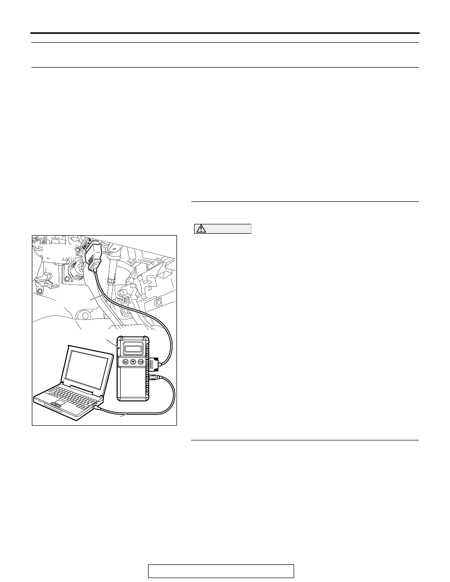
STEP 1. Using scan tool MB991958, check the data list 
item 75: Cancel switch.

CAUTION

To prevent damage to scan tool MB991958, always turn the 
ignition switch to the "LOCK" (OFF) position before con-
necting or disconnecting scan tool MB991958. 
(1) Connect scan tool MB991958 to the data link connector 

(Refer to 

P.17-12

).

(2) Turn the ignition switch to the "ON" position.
(3) Set scan tool MB991958 to data reading mode for cruise 

control system (Refer to 

P.17-12

).

• Item 75: Cancel switch.

• When the "CANCEL" switch is pressed, the display 

on scan tool MB991958 should be "ON".

• When the "CANCEL" switch is released, the display 

on scan tool MB991958 should be "OFF".

Q: Is the switch operating properly?

YES : Go to Step 2.
NO :  Repair the cruise control switch system (Refer to 

P.17-16

, Diagnosis Code Procedures 

− DTC 15: 

Cruise Control Switch System.) Then go to Step 3 .

STEP 2. Check the symptom.
Q: When the "CANCEL" switch is pressed, is the cruise 

control cancelled?
YES : 
It can be assumed that this malfunction is intermittent 

(Refer to GROUP 00, How to Use 
Troubleshooting/Inspection Service Points 

− How to 

Cope with Intermittent Malfunctions 

P.00-15

).

NO :  Replace the ECM [Refer to GROUP 13A, Engine 

Control Module (ECM) 

P.13A-887

] <2.4L Engine> or 

[Refer to GROUP 13B, Engine Control Module (ECM) 

P.13B-904

] <3.0L Engine>. Then go to Step 3.

ZC501967

AC404789

AC703911AB

MB991824

MB991827

MB991910

Data link

connector

CRUISE CONTROL

TSB Revision

ENGINE AND EMISSION CONTROL

17-46

STEP 3. Check the symptom.
Q: When the "CANCEL" switch is pressed, is the cruise 

control cancelled?
YES : 
The procedure is complete.
NO :  Return to Step 1.

Inspection Procedure 4: Cruise Control cannot be Set (No Response "COAST/SET" Switch and 
"ACC/RES" Switch is Pressed).

.

COMMENT

The fail-safe function is probably canceling cruise 
control system. In this case, checking the cruise con-
trol system, MFI system, CVT system <2.4L Engine> 
or A/T system <3.0L Engine>, ASC system <vehicles 
with ASC> and CAN bus line system for DTCs. The 
scan tool MB991958 can also be used to check if the 
circuits of each input switch are normal or not by 
checking the data list.
NOTE: Press the cruise control switches one by one 
securely. Otherwise, the cruise control system may 
not be started.

.

TROUBLESHOOTING HINTS (THE MOST 
LIKELY CAUSES FOR THIS CASE:)

• Malfunction of the CAN bus line system.

• Malfunction of the MFI system.

• Malfunction of the CVT system <2.4L Engine>.

• Malfunction of the A/T system<3.0L Engine>.

• Malfunction of the ASC system <vehicles with 

ASC>.

• Malfunction of the cruise control switch.

• Malfunction of the stoplight switch.

• Malfunction of the transmission range switch.

• Malfunction of the TCM.

• Malfunction of the ECM.

DIAGNOSTIC PROCEDURE

Required Special Tools:

• MB991958: Scan Tool (M.U.T.-III Sub Assembly)

• MB991824: V.C.I.

• MB991827: M.U.T.-III USB Cable

• MB991910: M.U.T.-III Main Harness A

CAUTION

If there is any problem in the CAN bus lines, an incorrect 
DTC may be set. Prior to this diagnosis, diagnose the CAN 
bus lines (Refer to GROUP 54C, Trouble code diagnosis 

P.54C-11

.)

CRUISE CONTROL

TSB Revision

ENGINE AND EMISSION CONTROL

17-47

STEP 1. Using scan tool MB991958, diagnose the CAN bus 
line.

CAUTION

To prevent damage to scan tool MB991958, always turn the 
ignition switch to the "LOCK" (OFF) position before con-
necting or disconnecting scan tool MB991958.
(1) Connect scan tool MB991958 to the data link connector 

(Refer to 

P.17-12

).

(2) Turn the ignition switch to the "ON" position.
(3) Set scan tool MB991958 to diagnose the CAN bus line 

(Refer to 

P.17-12

).

Q: Is the check result satisfactory?

YES : Go to Step 2.
NO :  Repair the CAN bus lines (Refer to GROUP 54C, 

Diagnosis 

− CAN Bus Diagnostics Chart 

P.54C-19

). 

Then go to Step 12.

STEP 2. Using scan tool MB991958, check for ECM option 
coding data.
(1) Connect scan tool MB991958 to the data link connector 

(Refer to 

P.17-12

.)

(2) Turn the ignition switch to the "ON" position.
(3) Check for ECM option coding data (Refer to GROUP 00, 

Precautions Before Service 

− Coding List 

P.00-44

.)

Q: Is the cruise control item of the ECM option coding data 

enabled?
YES : 
Go to Step 3.
NO :  Set the ECM option coding data again. (Refer to 

GROUP 00, Precautions Before Service 

− Coding List 

P.00-44

.) Then go to Step 12.

ZC501967

AC404789

AC703911AB

MB991824

MB991827

MB991910

Data link

connector

CRUISE CONTROL

TSB Revision

ENGINE AND EMISSION CONTROL

17-48

STEP 3. Using scan tool MB991958, read the MFI system 
DTC.
(1) Connect scan tool MB991958 to the data link connector 

(Refer to 

P.54C-19

).

(2) Turn the ignition switch to the "ON" position.
(3) Set scan tool MB991958 to check for MFI system DTC 

(Refer to GROUP 13A, MFI Diagnosis 

− Diagnostic 

Function 

P.13A-11

) <2.4L Engine> or (Refer to GROUP 

13B, MFI Diagnosis 

− Diagnostic Function 

P.13B-11

) <3.0L 

Engine>.

Q: Is any DTC set?

YES : Repair the MFI system (Refer to GROUP 13A, MFI 

Diagnosis 

− Diagnostic Trouble Code Chart 

P.13A-49

) <2.4L Engine> or (Refer to GROUP 13B, 

MFI Diagnosis 

− Diagnostic Trouble Code Chart 

P.13B-50

) <3.0L Engine>. Then go to Step 12.

NO :  Go to Step 4 <2.4L Engine>.
NO :  Go to Step 5 <3.0L Engine>.

STEP 4. Using scan tool MB991958, read the CVT system 
DTC <2.4L Engine>.
(1) Connect scan tool MB991958 to the data link connector 

(Refer to 

P.17-12

).

(2) Turn the ignition switch to the "ON" position.
(3) Set scan tool MB991958 to check for CVT system DTC 

(Refer to GROUP 23A, Diagnosis 

− Diagnostic Function 

P.23A-13

).

Q: Is any DTC set?

YES : Repair the CVT system (Refer to GROUP 23A, 

Diagnosis 

− Diagnostic Trouble Code Chart 

P.23A-27

). Then go to Step 12.

NO :  Go to Step 6.

STEP 5. Using scan tool MB991958, read the A/T system 
DTC <3.0L Engine>.
(1) Connect scan tool MB991958 to the data link connector 

(Refer to 

P.17-12

).

(2) Turn the ignition switch to the "ON" position.
(3) Set scan tool MB991958 to check for A/T system DTC 

(Refer to GROUP 23C, Automatic Transaxle Diagnosis 

− 

Diagnostic Function 

P.23C-20

).

Q: Is any DTC set?

YES : Repair the A/T system (Refer to GROUP 23C, 

Automatic Transaxle Diagnosis 

− Diagnostic Trouble 

Code Chart 

P.23C-166

). Then go to Step 12.

NO :  Go to Step 6 <vehicles with ASC>.
NO :  Go to Step 7 <vehicles without ASC>.


Content   ..  1597  1598  1599  1600   ..