Mitsubishi Outlander GS45X. Manual - part 1579


  Index      Mitsubishi     Mitsubishi Outlander GS45X - service repair manual


Search            


Content   ..  1577  1578  1579  1580   ..


Mitsubishi Outlander GS45X. Manual - part 1579


ENGINE COOLING DIAGNOSIS

TSB Revision

ENGINE COOLING

14-19

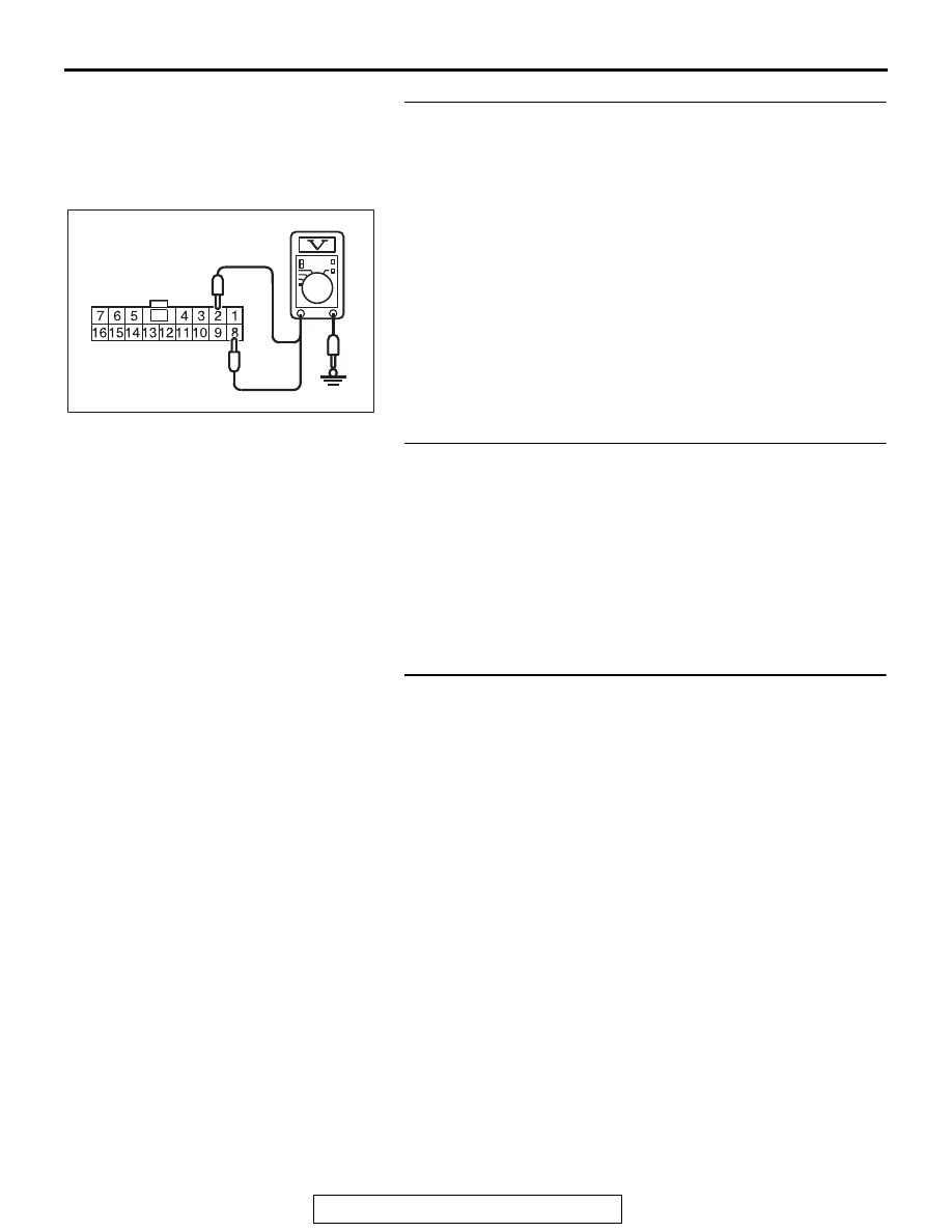
STEP 7. Measure the terminal voltage at ETACS-ECU 
connector C-312. 
(1) Disconnect the ETACS-ECU connector C-312 and measure 

at the harness connector side.

(2) Turn the ignition switch to the "ON" position.
(3) Measure the terminal voltage between ETACS-ECU 

connector C-312 terminal number 2 and body ground, and 
between ETACS-ECU connector C-312 terminal number 8 
and body ground.

OK: Battery positive voltage.

Q: Is the measured voltage battery positive voltage?

YES : Go to Step 13.
NO :  Go to Step 8.

STEP 8. Check the radiator fan relay connector A-34X, 
condenser fan relay connector A-35X, fan control relay 
connector A-36X, and ETACS-ECU connector C-312, for 
loose, corroded or damaged terminals, or terminals 
pushed back in the connector. 
Refer to GROUP 00E, Harness Connector Inspection 

P.00E-2

.

Q: Are the connectors and terminals in good condition?

YES : Go to Step 9.
NO :  Repair or replace the damaged connectors or replace 

the relay box. Then go to Step 23.

STEP 9. Check the harness wire between fusible link 
number 28 and condenser fan relay connector A-35X 
terminal number 3, between fusible link number 28 and 
condenser fan relay connector A-35X terminal number 4, 
between condenser fan relay connector A-35X terminal 
number 4 and fan control relay connector A-36X terminal 
number 1, and between fusible link number 29 and radiator 
fan relay connector A-34X terminal number 3, for damage.
Check harness wire for open/short circuit and damage.
Q: Are the harness wires in good condition?

YES : Go to Step 10.
NO :  Repair or replace the damaged harness wire. Then go 

to Step 23.

ACA02108 AD

C-312 Harness connector:
Component side

ENGINE COOLING DIAGNOSIS

TSB Revision

ENGINE COOLING

14-20

STEP 10. Check the harness wire between radiator fan 
relay connector A-34X terminal number 1 and ETACS-ECU 
connector C-312 terminal number 2, between condenser 
fan relay connector A-35X terminal number 1 and 
ETACS-ECU connector C-312 terminal number 8, and 
between fan control relay connector A-36X terminal 
number 3 and ETACS-ECU connector C-312 terminal 
number 8, for damage.
Check harness wire for open/short circuit and damage.
Q: Are the harness wires in good condition?

YES : Go to Step 11.
NO :  Repair or replace the damaged harness wire. Then go 

to Step 23.

STEP 11. Check the radiator fan relay, the condenser fan 
relay and the fan control relay. 
Refer to 

P.14-31

.

Q: Are the relays in good condition?

YES : Go to Step 12.
NO :  Replace the damaged relay. Then go to Step 23.

STEP 12. Check the fusible link number 28 and fusible link 
number 29.
Q: Are the fusible links in good condition?

YES : Go to Step 20.
NO :  Replace the damaged fusible link. Then go to Step 

23.

STEP 13. Check the radiator fan relay connector A-34X, 
condenser fan relay connector A-35X, fan control relay 
connector A-36X, radiator fan motor connector A-05, and 
condenser fan motor connector A-43, for loose, corroded 
or damaged terminals, or terminals pushed back in the 
connector.
Refer to GROUP 00E, Harness Connector Inspection 

P.00E-2

.

Q: Are the connectors and terminals in good condition?

YES : Go to Step 14.
NO :  Repair or replace the damaged connectors or replace 

the relay box. Then go to Step 23.

STEP 14. Check the harness wire between fusible link 
number 28 and condenser fan relay connector A-35X 
terminal number 4, and between fusible link number 29 
and radiator fan relay connector A-34X terminal number 4, 
for damage.
Check harness wire for open/short circuit and damage.
Q: Are the harness wires in good condition?

YES : Go to Step 15.
NO :  Repair or replace the damaged harness wire. Then go 

to Step 23.

ENGINE COOLING DIAGNOSIS

TSB Revision

ENGINE COOLING

14-21

STEP 15. Check the harness wire between radiator fan 
relay connector A-34X terminal number 2 and radiator fan 
motor connector A-05 terminal number 1, and between 
condenser fan relay connector A-35X terminal number 2 
and condenser fan motor connector A-43 terminal number 
1, for damage.
Check harness wire for open/short circuit and damage.
Q: Are the harness wires in good condition?

YES : Go to Step 16.
NO :  Repair or replace the damaged harness wire. Then go 

to Step 23.

STEP 16. Check the harness wire between radiator fan 
motor connector A-05 terminal number 2 and fan control 
relay connector A-36X terminal number 2, and between 
condenser fan motor connector A-43 terminal number 2 
and body ground, for damage.
Check harness wire for open/short circuit and damage.
Q: Is the check result normal?

YES : Go to Step 17.
NO :  Repair or replace the damaged harness wire. Then go 

to Step 23.

STEP 17. Check the harness wire between fan control relay 
connector A-36X terminal number 4 and condenser fan 
relay connector A-35X terminal number 2, and between fan 
control relay connector A-36X terminal number 5 and body 
ground, for damage.
Check harness wire for open/short circuit and damage.
Q: Are the harness wires in good condition?

YES : Go to Step 18.
NO :  Repair or replace the damaged harness wire. Then go 

to Step 23.

STEP 18. Check the radiator fan relay, the condenser fan 
relay and the fan control relay.
Refer to 

P.14-31

.

Q: Are the relays in good condition?

YES : Go to Step 19.
NO :  Replace the damaged relay. Then go to Step 23.

STEP 19. Check the radiator fan motor and the condenser 
fan motor. 
Refer to 

P.14-33

.

Q: Are the fan motors in good condition?

YES : Go to Step 20.
NO :  Replace the damaged fan motor (Refer to 

P.14-52

). 

Then go to Step 23.

ENGINE COOLING DIAGNOSIS

TSB Revision

ENGINE COOLING

14-22

STEP 20. Using scan tool MB991958, read the ETACS 
system DTC.
Using scan tool to read the ETACS system DTC (Refer to 
GROUP 54A, ETACS, Troubleshooting 

− Diagnostic Function 

P.54A-729

).

Q: Is any DTC set?

YES : Replace the ETACS-ECU (Refer to GROUP 54A, 

ETACS 

− ETACS-ECU 

P.54A-825

). Then go to Step 

23.

NO :  Go to Step 21.

STEP 21. Using scan tool MB991958, check the MFI system 
actuator test.
Using scan tool to check the MFI system actuator test (Refer to 
GROUP 13B, MFI Diagnosis 

− Diagnostic Function 

P.13B-11

).

• Item 14: Cooling fan

(Refer to GROUP 13B, MFI Diagnosis 

− Actuator Test Ref-

erence Table 

P.13B-858

)

Q: Is the check result normal?

YES : Go to Step 22.
NO :  Replace the ECM [Refer to GROUP 13B, Engine 

Control Module (ECM) 

P.13B-903

]. Then go to Step 

23.

STEP 22. Check the symptom.
Q: Does the radiator fan and condenser fan operate 

normal?
YES : 
An intermittent malfunction is suspected (Refer to 

GROUP 00, How to use troubleshooting 

− How to 

Cope with Intermittent Malfunction 

P.00-15

).

NO :  Replace the ECM [Refer to GROUP 13B, Engine 

Control Module (ECM) 

P.13B-903

]. Then go to Step 

23.

STEP 23. Check the symptom.
Q: Does the radiator fan and condenser fan operate 

normal?
YES : 
The procedure is complete.
NO :  Return to Step 1.


Content   ..  1577  1578  1579  1580   ..