Content .. 1487 1488 1489 1490 ..
Mitsubishi Outlander GS45X. Manual - part 1489
SIDE IMPACT SENSOR
TSB Revision
SUPPLEMENTAL RESTRAINT SYSTEM (SRS)
52B-451
NOTE: The illustration above shows the side impact
sensor (RH). The position of the side impact sensor
(LH) is symmetrical to this.
REMOVAL SERVICE POINTS
.
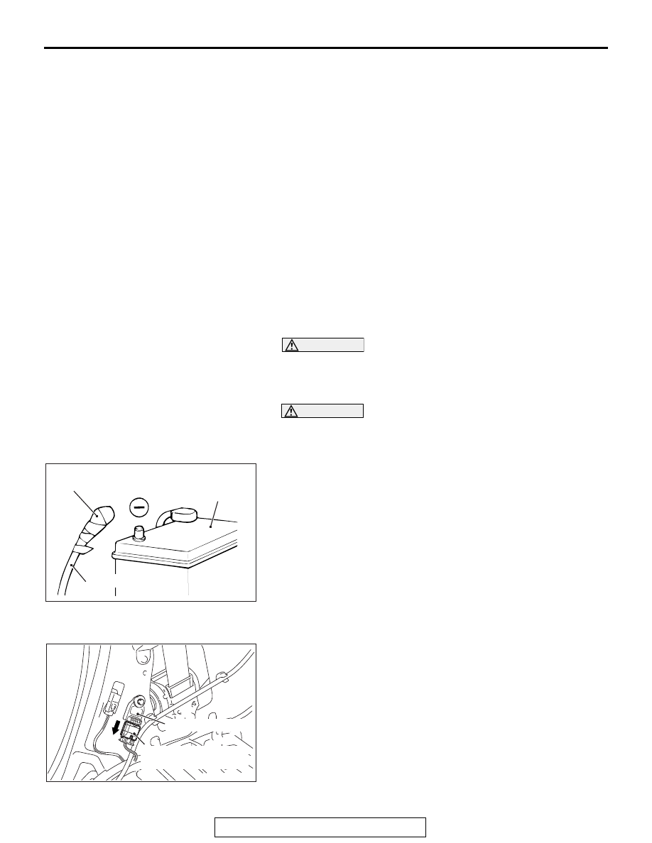
<<A>> NEGATIVE (
−) BATTERY CABLE DISCON-
NECTION
DANGER
Wait at least 60 seconds after disconnecting the bat-
tery cable before doing any further work (Refer to
).
WARNING
Battery posts, terminals and related accessories con-
tain lead and lead compounds. WASH HANDS AFTER
HANDLING.
Disconnect the negative (
−) battery cable from the battery and
tape the terminal to prevent accidental connection and air bag
deployment.
.
<<B>> IMPACT SENSOR CONNECTOR REMOVAL
Slide the outer housing of the impact sensor connector in the
arrow direction shown, and disconnect the connector.
NOTE: The illustration shows the side impact sensor (rear). As
for the impact sensor (front), follow the same procedure.
Side impact sensor (Rear)
installation steps
>>A<<
•
Pre-installation inspection
>>B<<
3.
Side impact sensor (Rear)
•
Side impact sensor connector
connection
•
Quarter trim, lower (Refer to
GROUP 52A, Interior Trim
1.
Negative (
−) battery cable
connection
>>C<<
•
Post-installation inspection
ACX00583
Insulating tape
Battery cable
Battery
AF
AC701973
Side impact sensor
Outer housing of the
impact sensor connector
AB