Content .. 1478 1479 1480 1481 ..
Mitsubishi Outlander GS45X. Manual - part 1480
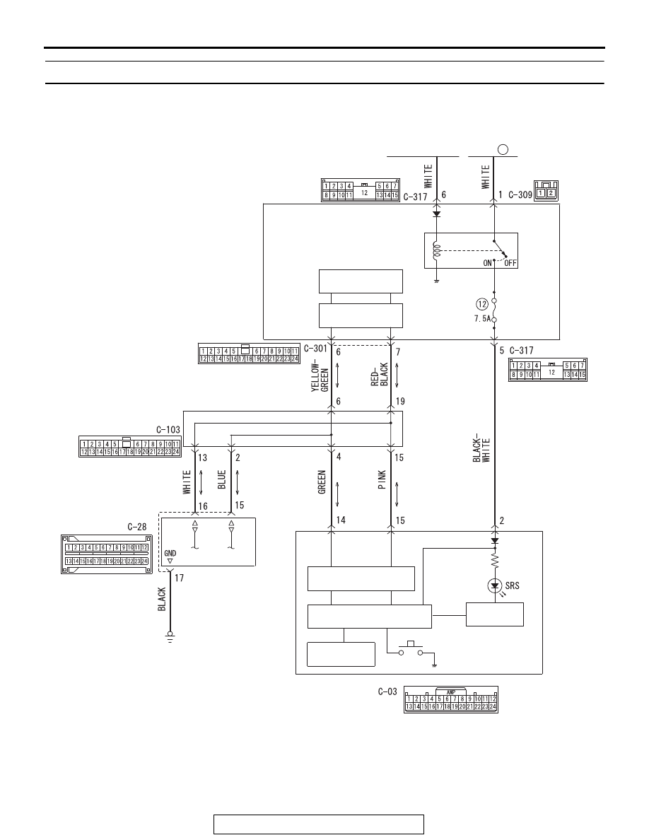
SRS AIR BAG DIAGNOSIS
TSB Revision
SUPPLEMENTAL RESTRAINT SYSTEM (SRS)
52B-415
Inspection procedure 3:The SRS Warning Light does not Illuminate.
IG1
RELAY
AC901209
ETACS-ECU
COMBINATION METER
FUSIBLE
LINK
34
CAN DRIVE
CIRCUIT
IGNITION
SWITCH (IG1)
INTERFACE
CIRCUIT
JOINT CONNECTOR
(CAN1)
SRS-ECU
SRS Warning Light Circuit
AC
CAN TRANSCEIVER
CIRCUIT
LED DRIVE
CIRCUIT
CPU
LCD (SRS)
RHEOSTAT