Mitsubishi Outlander GS45X. Manual - part 1439


  Index      Mitsubishi     Mitsubishi Outlander GS45X - service repair manual


Search            


Content   ..  1437  1438  1439  1440   ..


Mitsubishi Outlander GS45X. Manual - part 1439


SRS AIR BAG DIAGNOSIS

TSB Revision

SUPPLEMENTAL RESTRAINT SYSTEM (SRS)

52B-251

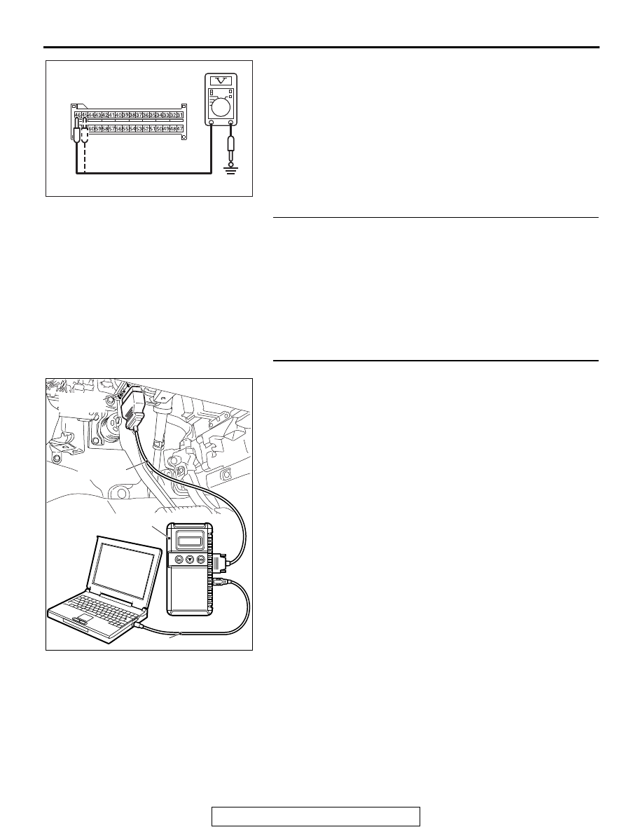
(7) Measure the voltage between C-27 harness side connector 

terminals 45, 46 and body ground.
Voltage should measure 1 volt or less.

Q: Is the measured voltage within the specified range?

YES : Erase the diagnostic trouble code memory, and check 

the diagnostic trouble code. If DTC B1C39 sets, 
replace the SRS-ECU (Refer to 

P.52B-436

). Then go 

to Step 6.

NO :  Go to Step 5.

STEP 5. Check the harness wires for short circuit to power 
supply between SRS-ECU connector C-27 (terminal No.45 
and 46) and driver's seat belt pre-tensioner connector 
D-121 (terminal No.1 and 2).
Q: Is the check result normal?

YES : Go to Step 6.
NO :  Repair the harness wires between SRS-ECU 

connector C-27 and driver's seat belt pre-tensioner 
connector D-121. Then go to Step 6.

STEP 6. Recheck for diagnostic trouble code. 
Check again if the DTC is set.
(1) Erase the DTC.
(2) Turn the ignition switch to the "ON" position.
(3) Check if the DTC is set.
(4) Turn the ignition switch to the "LOCK" (OFF) position.
Q: Is DTC B1C39 set?

YES : Return to Step 1. 
NO :  The procedure is complete.

AC608813

C-27 Harness side 
connector (front view)

CA

ZC501967

AC404789

AC701411AB

MB991824

MB991827

MB991910

Data link 
connector

SRS AIR BAG DIAGNOSIS

TSB Revision

SUPPLEMENTAL RESTRAINT SYSTEM (SRS)

52B-252

 DTC B1C3A: Driver's Seat Belt Pre-tensioner (Squib) System (Squib Circuit Open)

CAUTION

If DTC B1C3A is set in the SRS-ECU, always diag-
nose the CAN main bus line.

.

CIRCUIT OPERATION

The SRS-ECU judges how severe a collision is by 
detecting signals from the front impact sensors and 
the front air bag analog G-sensor. If the impact is 
over a predetermined level, the SRS-ECU sends an 
ignition signal. At this time, if the front air bag safing 
G-sensor is on, the pre-tensioner will deploy. 

.

DTC SET CONDITIONS

This DTC is set if there is abnormal resistance 
between the input terminals of the driver's seat belt 
pre-tensioner (squib).

.

TROUBLESHOOTING HITS

• Improper connector contact

• Open circuit in the driver's seat belt pre-tensioner 

(squib) circuit

• Malfunction of the SRS-ECU

: CONNECTOR COUPLED: ON
  CONNECTOR UNCOUPLED: OFF

NOTE

Seat Belt Pre-Tensioner (Driver's side) (Squib) Circuit

SRS-ECU

SEAT BELT 
PRE-TENSIONER 
(LH)

CONNECTOR 
LOCK SWITCH

CONNECTOR 
LOCK 
SWITCH

AC901076

C-27 (Y)

AC

Connector: C-27

AC901080AD

Connector: D-121

D-121 (B)

SRS AIR BAG DIAGNOSIS

TSB Revision

SUPPLEMENTAL RESTRAINT SYSTEM (SRS)

52B-253

DIAGNOSIS

Required Special Tools:

• MB991958: Scan Tool (M.U.T.-III Sub Assembly)

• MB991824: Vehicle Communication Interface (V.C.I.)

• MB991827: M.U.T.-III USB Cable

• MB991910: M.U.T.-III Main Harness A (Vehicles with 

CAN Communication System)

• MB991865: Dummy resistor

• MB991884: Resister harness

STEP 1. Using scan tool MB991958, diagnose the CAN bus 
line.

CAUTION

To prevent damage to scan tool MB991958, always turn the 
ignition switch to the "LOCK" (OFF) position before con-
necting or disconnecting scan tool MB991958.
(1) Connect scan tool MB991958. Refer to "How to connect the 

scan tool 

P.52B-28

."

(2) Turn the ignition switch to the "ON" position.
(3) Diagnose the CAN bus line.
(4) Turn the ignition switch to the "LOCK" (OFF) position.
Q: Is the CAN bus line found to be normal?

YES : Go to Step 2.
NO :  Repair the CAN bus line (Refer to GROUP 54C, 

Diagnosis 

P.54C-17

).

ZC501967

AC404789

AC701411AB

MB991824

MB991827

MB991910

Data link 
connector

SRS AIR BAG DIAGNOSIS

TSB Revision

SUPPLEMENTAL RESTRAINT SYSTEM (SRS)

52B-254

STEP 2. Recheck for diagnostic trouble code.
Check again if the DTC is set.
(1) Erase the DTC.
(2) Turn the ignition switch to the "ON" position.
(3) Check if the DTC is set.
(4) Turn the ignition switch to the "LOCK" (OFF) position.
Q: Is the DTC set?

YES : Go to Step 3.
NO :  There is an intermittent malfunction such as poor 

engaged connector(s) or open circuit (Refer to 
GROUP 00, How to Cope with Intermittent 
Malfunction 

P.00-15

).

STEP 3. Check the driver's seat belt pre-tensioner. (Using 
scan tool MB991958, read the diagnostic trouble code.)
(1) Disconnect the negative battery terminal.
(2) Disconnect driver's seat belt pre-tensioner connector 

D-121. Use a flat-tipped screwdriver to unlock the locking 
button at the harness side connector by withdrawing it 
toward you in two stages, and then disconnect the 
connector.

(3) Connect special tool MB991865 to special tool MB991884.
(4) Connect special tool MB991884 to the D-121 harness side 

connector.

(5) Connect the negative battery terminal.
(6) Erase diagnostic trouble code memory, and then check the 

diagnostic trouble code.

Q: Is DTC B1C3A set?

YES : Go to Step 4.
NO :  Replace the driver's seat belt with pre-tensioner 

(Refer to 

P.52B-457

). Then go to Step 5

ZC501967

AC404789

AC701411AB

MB991824

MB991827

MB991910

Data link 
connector

AC507550AE

Seat belt 
pre-tensioner

Harness side
connector

Locking 
button

Flat-tipped
screwdriver

AC301553 BE

Harness side 
connector

MB991865

(Dummy resistor: 3    )

MB991884 

(Resistor harness)


Content   ..  1437  1438  1439  1440   ..