Mitsubishi Outlander GS45X. Manual - part 1433


  Index      Mitsubishi     Mitsubishi Outlander GS45X - service repair manual


Search            


Content   ..  1431  1432  1433  1434   ..


Mitsubishi Outlander GS45X. Manual - part 1433


SRS AIR BAG DIAGNOSIS

TSB Revision

SUPPLEMENTAL RESTRAINT SYSTEM (SRS)

52B-227

DIAGNOSIS

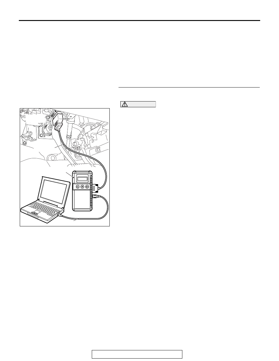
Required Special Tools:

• MB991958: Scan Tool (M.U.T.-III Sub Assembly)

• MB991824: Vehicle Communication Interface (V.C.I.)

• MB991827: M.U.T.-III USB Cable

• MB991910: M.U.T.-III Main Harness A (Vehicles with 

CAN Communication System)

• MB991865: Dummy resistor

• MB991884: Resister harness

STEP 1. Using scan tool MB991958, diagnose the CAN bus 
line.

CAUTION

To prevent damage to scan tool MB991958, always turn the 
ignition switch to the "LOCK" (OFF) position before con-
necting or disconnecting scan tool MB991958.
(1) Connect scan tool MB991958. Refer to "How to connect the 

scan tool 

P.52B-28

."

(2) Turn the ignition switch to the "ON" position.
(3) Diagnose the CAN bus line.
(4) Turn the ignition switch to the "LOCK" (OFF) position.
Q: Is the CAN bus line found to be normal?

YES : Go to Step 2.
NO :  Repair the CAN bus line (Refer to GROUP 54C, 

Diagnosis 

P.54C-17

).

ZC501967

AC404789

AC701411AB

MB991824

MB991827

MB991910

Data link 
connector

SRS AIR BAG DIAGNOSIS

TSB Revision

SUPPLEMENTAL RESTRAINT SYSTEM (SRS)

52B-228

STEP 2. Recheck for diagnostic trouble code.
Check again if the DTC is set.
(1) Erase the DTC.
(2) Turn the ignition switch to "ON" position.
(3) Check if the DTC is set.
(4) Turn the ignition switch to the "LOCK" (OFF) position.
Q: Is the DTC set?

YES : Go to Step 3.
NO :  Go to Step 6.

STEP 3. Check the lap pre-tensioner. (Using scan tool 
MB991958, read the diagnostic trouble code.)
(1) Disconnect the negative battery terminal.
(2) Disconnect lap pre-tensioner connector D-24. Use a 

flat-tipped screwdriver to unlock the locking button at the 
harness side connector by withdrawing it toward you in two 
stages, and then disconnect the connector.

(3) Connect special tool MB991865 to special tool MB991884.
(4) Connect special tool MB991884 to the D-24 harness side 

connector.

(5) Connect the negative battery terminal.
(6) Erase diagnostic trouble code memory, and check the 

diagnostic trouble code.

Q: Is DTC B1C34 set?

YES : Go to Step 4.
NO :  Replace the driver's seat belt with pre-tensioner. 

(Refer to 

P.52B-457

). Then go to Step 6.

ZC501967

AC404789

AC701411AB

MB991824

MB991827

MB991910

Data link 
connector

AC701629 AB

Harness side 
connector

Locking button

Flat-tipped 
screwdriver

Lap pre-tensioner

AC301553 BE

Harness side 
connector

MB991865

(Dummy resistor: 3    )

MB991884 

(Resistor harness)

SRS AIR BAG DIAGNOSIS

TSB Revision

SUPPLEMENTAL RESTRAINT SYSTEM (SRS)

52B-229

STEP 4. Check the lap pre-tensioner circuit. Measure the 
voltage at the SRS-ECU connector C-27.
(1) Disconnect the negative battery terminal.
(2) While pushing the part "A" indicated in the figure of the 

harness side connector, turn the lock lever to the direction 
of the arrow to release the lock lever, and disconnect the 
C-27 SRS-ECU connector.

DANGER

To prevent the lap pre-tensioner from deploying unin-
tentionally, disconnect the lap pre-tensioner connec-
tor D-24 to short the squib circuit.

(3) Disconnect lap pre-tensioner connector D-24. Use a 

flat-tipped screwdriver to unlock the locking button at the 
harness side connector by withdrawing it toward you in two 
stages, and then disconnect the connector.

CAUTION

Insert an insulator such as a cable tie to a depth of 4mm 
(0.16 inch) or more, otherwise the short spring will not be 
released.
(4) Insert a cable tie [3 mm (0.12 inch) wide, 0.5 mm (0.02 inch) 

thick] between terminals 35, 36 and the short spring to 
release the short spring.

(5) Connect the negative battery terminal.
(6) Ignition switch: "ON".

AC507645

A

AC

Lock lever

AC701629 AB

Harness side 
connector

Locking button

Flat-tipped 
screwdriver

Lap pre-tensioner

AC507303AM

A

A

C-27 Harness side
connector (front view)

Section
A - A

Cable tie

Short spring

4 mm or more

Terminal

SRS AIR BAG DIAGNOSIS

TSB Revision

SUPPLEMENTAL RESTRAINT SYSTEM (SRS)

52B-230

(7) Measure the voltage between C-27 harness side connector 

terminals 35, 36 and body ground.
Voltage should measure 1 volt or less.

Q: Is the measured voltage within the specified range?

YES : Erase the diagnostic trouble code memory, and check 

the diagnostic trouble code. If DTC B1C34 sets, 
replace the SRS-ECU (Refer to 

P.52B-436

). Then go 

to Step 6.

NO :  Go to Step 5.

STEP 5. Check the harness wires for short circuit to power 
supply between SRS-ECU connector C-27 (terminal No.35 
and 36) and lap pre-tensioner connector D-24 (terminal 
No.2 and 1).
Q: Is the check result normal?

YES : Go to Step 6.
NO :  Repair the harness wires between SRS-ECU 

connector C-27 and lap pre-tensioner connector 
D-24. Then go to Step 6.

STEP 6. Recheck for diagnostic trouble code. 
Check again if the DTC is set.
(1) Erase the DTC.
(2) Turn the ignition switch to the "ON" position.
(3) Check if the DTC is set.
(4) Turn the ignition switch to the "LOCK" (OFF) position.
Q: Is DTC B1C34 set?

YES : Return to Step 1. 
NO :  The procedure is complete.

AC608813

C-27 Harness side 
connector (front view)

BZ

ZC501967

AC404789

AC701411AB

MB991824

MB991827

MB991910

Data link 
connector


Content   ..  1431  1432  1433  1434   ..