Content .. 1391 1392 1393 1394 ..
Mitsubishi Outlander GS45X. Manual - part 1393
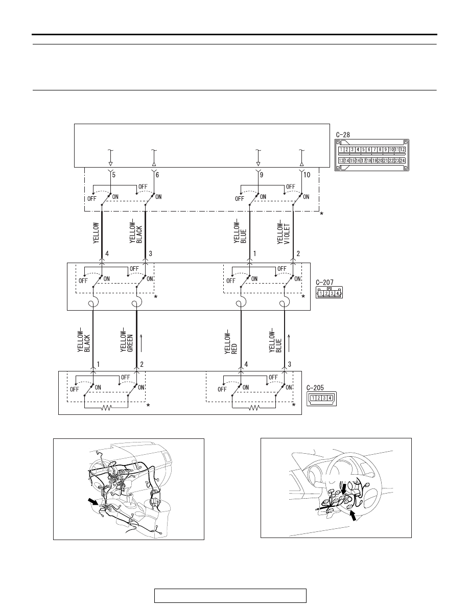
SRS AIR BAG DIAGNOSIS
TSB Revision
SUPPLEMENTAL RESTRAINT SYSTEM (SRS)
52B-67
DTC B1B03: Driver's Air Bag Module (1st squib) System (Short Circuit Between Squib Circuit
Terminals)
DTC B1B07: Driver's Air Bag Module (2nd squib) System (Short Circuit Between Squib Circuit
Terminals)
AC701509
SRS-ECU
DRIVER'S AIR BAG
MODULE (SQUIB)
CLOCK
SPRING
Drivers's Air Bag Module (Squib) Circuit
*: CONNECTOR LOCK SWITCH
CONNECTOR COUPLED: ON
CONNECTOR UNCOUPLED: OFF
NOTE
AB
AC901076
C-28 (Y)
AB
Connector: C-28
AC900844
C-205 (Y)
C-207 (Y)
Connectors: C-205, C-207
AL