Mitsubishi Outlander GS45X. Manual - part 1324


  Index      Mitsubishi     Mitsubishi Outlander GS45X - service repair manual


Search            


Content   ..  1322  1323  1324  1325   ..


Mitsubishi Outlander GS45X. Manual - part 1324


DIAGNOSIS

TSB Revision

ELECTRONIC CONTROL AWD

27C-19

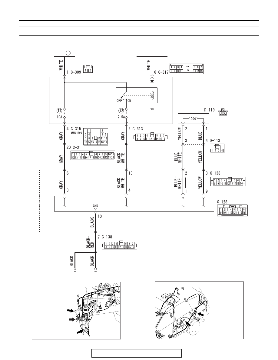
DTC C145A: Wiring harness and coupling coil short circuit failure

ELECTRONIC
CONTROL
COUPLING
SOLENOID

ETACS-ECU

FUSIBLE
LINK

34

IGNITION
SWITCH (IG1)

IG1
RELAY

AWD-ECU

ACA02787

AC901227AB

C-128

C-31

C-138

Connectors: C-31, C-128, C-138

AC901229AB

Connectors: D-113, D119

D-113

D-119

DIAGNOSIS

TSB Revision

ELECTRONIC CONTROL AWD

27C-20

CAUTION

If there is any problem in the CAN bus lines, an 
incorrect DTC may be set. Prior to this diagnosis, 
always diagnose the CAN bus lines.

.

OPERATION

If the current flowing the electronic control coupling 
solenoid coil is larger than the command value from 
AWD-ECU, the system is deactivated.

.

DTC SET CONDITIONS

If the following conditions are met when the system 
is activated, AWD-ECU switches the control from 
AWD to FWD, flashes the AWD/LOCK indicators 
alternately, and sets the DTC C145A.

• Sets the specified current command value to the 

electronic control coupling solenoid

• Drive current value of the electronic control cou-

pling solenoid: Deviated over from the normal 
current range

.

TROUBLESHOOTING HINTS

Current trouble

• Short circuit inside the electronic control coupling 

solenoid

• Wiring harness or connector failure (short circuit 

between the electronic control coupling solenoid 
terminals)

• Damaged wiring harness and connectors

• Short to ground between AWD-ECU and the 

electronic control coupling solenoid

• AWD-ECU internal error

Past trouble

• Intermittent wiring harness or connector failure

NOTE: For diagnosis procedures, refer to "How 
to treat past trouble" (Refer to GROUP 00 

 How 

to Use Troubleshooting/How to Treat Past Trou-
ble 

P.00-17

).

• Intermittent electronic control coupling failure 

(solenoid failure)

DIAGNOSIS

• MB991958: Scan Tool (M.U.T.-III Sub Assembly)

• MB991824: Vehicle Communication Interface

• MB991827: M.U.T.-III USB Cable

• MB991910: M.U.T.-III Main Harness A

STEP 1. Scan tool MB991958 CAN bus diagnostics
Use scan tool MB991958 to diagnose the CAN bus lines.
Q: Is the check result normal?

YES : Go to Step 3.
NO :  Repair the CAN bus line (Refer to GROUP 54C 

− 

Troubleshooting/CAN Bus Diagnostics Table 

P.54C-17

). On completion, go to Step 2.

AC901228AB

C-315

C-309
(B)

ETACS-ECU 
(front view)

Connectors: C309, C-315

DIAGNOSIS

TSB Revision

ELECTRONIC CONTROL AWD

27C-21

STEP 2. Check whether the DTC is reset after repairing the 
CAN bus line.
(1) Erase the DTC.
(2) Turn the ignition switch from the "LOCK" (OFF) position to 

the "ON" position and hold there for 2 seconds.

(3) Fully depress the accelerator pedal, and maintain its 

position for 2 seconds.
NOTE: The coupling coil electronic control is also based on 
the accelerator pedal opening degree, thus the signal is 
sent to the ECU.

(4) Check if the DTC is set.
Q: Is the DTC C145A set?

YES : Go to Step 3.
NO :  The procedure is complete.

STEP 3. Scan tool MB991958 data list
Check the following data list (Refer to 

P.27C-90

).

• Item 04: Coupling current command value

• Item 05: Coupling current monitor value

Q: Is the check result normal?

YES : Go to Step 10.
NO :  Go to Step 4.

STEP 4. Check the following connector:
Check the connectors below for improper engagement, termi-
nal damage or terminal drawn in the connector case.

• C-128 AWD-ECU connector

• C-138 intermediate connector

• D-113 intermediate connector

• D-119 electronic control coupling solenoid connector

• C-31 intermediate connector

Q: Are the connectors and terminals in good condition?

YES : Go to Step 5.
NO :  Repair the connector(s) or terminal(s). Then go to 

Step 11.

STEP 5. Wiring harness check
Check the wiring harness between the C-128 AWD-ECU con-
nector and the C-138 intermediate connector, the wiring har-
ness between the C-138 intermediate connector and the D-113 
intermediate connector, and the wiring harness between the 
D-113 intermediate connector and the D-119 electronic control 
coupling solenoid side connector for damage or other problem.
Q: Is the wiring harness in good condition?

YES : Go to Step 6.
NO :  Repair damage or other problem in the wiring 

harness. Then go to Step 11.

DIAGNOSIS

TSB Revision

ELECTRONIC CONTROL AWD

27C-22

STEP 6. Resistance measurement between electronic 
control coupling solenoid connector (coupling side) 
terminals
Disconnect the D-119 connector, and measure the resistance 
value between the connector terminals on the electronic control 
coupling side.

Standard value: 2.2 

 4.0 Ω

Q: Is the measured resistance value within the standard 

value range?
YES : 
Go to Step 7.
NO :  Replace the electronic control coupling (Refer to 

P.27C-97

). Then go to Step 11.

STEP 7. Voltage measurement at the AWD-ECU connector
(1) Disconnect the C-128 AWD-ECU connector.
(2) Measure the voltage between the C-128 wiring harness 

side connector terminals No. 3, No.4 (Ignition switch "ON") 
and the body ground.

OK: System voltage

Q: Is the check result normal?

YES : Go to Step 8.
NO :  Go to Step 9.

STEP 8. Wiring harness check
Check the wiring harness between the C-128 AWD-ECU con-
nector (terminal No.10) and the body ground for damage or 
other problem.
Q: Is the wiring harness in good condition?

YES : Go to Step 10.
NO :  Repair the wiring harness. Then go to Step 11.

STEP 9. Wiring harness check
NOTE: Prior to the wiring harness inspection, check the C-309 
and C-315 ETACS-ECU connector, and repair if necessary.
Check the wiring harness between the C-128 AWD-ECU con-
nector (terminal No.3) and the fusible link No. 34, and the wir-
ing harness between the C-128 AWD-ECU connector [terminal 
No.4 (ignition switch "ON")] and the fusible link No. 34 for dam-
age or other problem.
Q: Is the wiring harness in good condition?

YES : Go to Step 10.
NO :  Repair the wiring harness. Then go to Step 11.


Content   ..  1322  1323  1324  1325   ..