Content .. 1288 1289 1290 1291 ..
Mitsubishi Outlander GS45X. Manual - part 1290
DIAGNOSIS
TSB Revision
CONTROLLER AREA NETWORK (CAN)
54C-105
.
FUNCTION
If a failure is present in the wiring harness between
the joint connector (CAN2) and the joint connector
(CAN3), this diagnosis result will be set.
.
TROUBLE JUDGMENT CONDITIONS
If a communication flag is not set for some of the
ECUs on the CAN-C line, the ETACS-ECU deter-
mines that there is a failure.
.
TROUBLESHOOTING HINTS
• Malfunction of the connector [joint connector
(CAN2), joint connector (CAN3) or intermediate
connector failed]
• Malfunction of the wiring harness [open circuit
between joint connector (CAN2) and joint con-
nector (CAN3)]
DIAGNOSIS
Required Special Tools:
• MB991223: Harness Set
• MB992006: Extra Fine Probe
STEP 1. Check joint connector (CAN2) C-04, joint
connector (CAN3) C-01 and intermediate connector C-33
for loose, corroded or damaged terminals, or terminals
pushed back in the connector.
CAUTION
The strand end of the twisted wire should be within 10 cm
(4 inches) from the connector. For details refer to
Q: Are joint connector (CAN2) C-04, joint connector (CAN3)
C-01 and intermediate connector C-33 in good
condition?
YES : Go to Step 2.
NO : Repair the damaged parts.
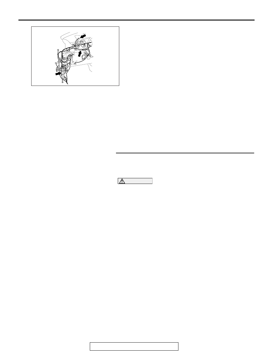
AC901075 AT
Connectors: C-01, C-04, C-33
C-01
C-04
C-33