Mitsubishi Outlander GS45X. Manual - part 1258


  Index      Mitsubishi     Mitsubishi Outlander GS45X - service repair manual


Search            


Content   ..  1256  1257  1258  1259   ..


Mitsubishi Outlander GS45X. Manual - part 1258


TROUBLESHOOTING

TSB Revision

LOCAL INTERCONNECT NETWORK (LIN)

54B-25

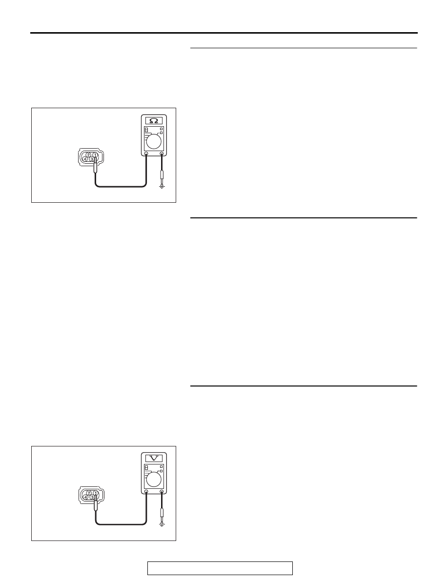
STEP 2. Check the ground circuit to the theft-alarm siren. 
Measure the resistance at theft-alarm siren connector 
A-62.
(1) Disconnect theft-alarm siren connector A-62 and measure 

the resistance available at the wiring harness side of the 
connector.

(2) Measure the resistance value between theft-alarm siren 

connector A-62 terminal 1 and ground.

• The resistance should be 2  or less.

Q: Is the measured resistance 2  or less?

YES : Go to Step 4.
NO :  Go to Step 3.

STEP 3. Check the wiring harness between theft-alarm 
siren connector A-62 (terminal 1) and the ground.
Check the ground wires for open circuit.
NOTE: Also check intermediate connector A-03 for loose, cor-
roded, or damaged terminals, or terminals pushed back in the 
connector. If intermediate connector A-03 is damaged, repair or 
replace the connector as described in GROUP 00E, Harness 
Connector Inspection 

P.00E-2

.

Q: Is the wiring harness between theft-alarm siren 

connector A-62 (terminal 1) and the ground in good 
condition?
YES : 
No action is necessary and testing is complete.
NO :  The wiring harness may be damaged or the 

connector(s) may have loose, corroded or damaged 
terminals, or terminals pushed back in the connector. 
Repair the wiring harness as necessary.

STEP 4. Check the battery power supply circuit to the 
theft-alarm siren. Measure the voltage at theft-alarm siren 
connector A-62.
(1) Disconnect theft-alarm siren connector A-62 measure the 

voltage available at the wiring harness side of the 
connector.

(2) Measure the voltage between theft-alarm siren connector 

A-62 terminal 1 and ground.

• The voltage should measure approximately 12 volts 

(battery positive voltage).

Q: Is the measured voltage approximately 12 volts (battery 

positive voltage)?
YES : 
Go to Step 6.
NO :  Go to Step 5.

AC608255 DG

Connector A-62
(Harness side)

AC608254 FB

Connector A-62
(Harness side)

TROUBLESHOOTING

TSB Revision

LOCAL INTERCONNECT NETWORK (LIN)

54B-26

STEP 5. Check the wiring harness between ETACS-ECU 
connector C-304 (terminal 4) and theft-alarm siren 
connector A-62 (terminal 2).

• Check the power supply line (battery supply) for open circuit 

and short circuit.

NOTE: Also check intermediate connector A-03 for loose, cor-
roded, or damaged terminals, or terminals pushed back in the 
connector. If intermediate connector A-03 is damaged, repair or 
replace the connector as described in GROUP 00E, Harness 
Connector Inspection 

P.00E-2

.

Q: Is the wiring harness between ETACS-ECU connector 

C-304 (terminal 4) and theft-alarm siren connector A-62 
(terminal 2) in good condition?
YES : 
No action is necessary and testing is complete.
NO :  The wiring harness may be damaged or the 

connector(s) may have loose, corroded or damaged 
terminals, or terminals pushed back in the connector. 
Repair the wiring harness as necessary.

STEP 6. Check the LIN cutoff control unit.
Remove the LIN cutoff control unit. Check for continuity 
between the following terminals and inspect the relay.

• Continuity check

• Relay check

Q: Is the LIN cutoff control unit in good condition?

YES : Go to Step 7.
NO :  Replace the LIN cutoff control unit.

Terminal number

Measurement value

5 to 3

Continuity exists (2 

Ω or 

less)

System voltage

Terminal 
number

Normal 
condition

At no energization

5 to 7

No 
continuity

With current supply 
[terminal 1 (+), terminal 8 
(

−)]

Continuity 
exists (2 

Ω 

or less)

TROUBLESHOOTING

TSB Revision

LOCAL INTERCONNECT NETWORK (LIN)

54B-27

STEP 7. Check the battery power supply circuit to the 
ETACS-ECU. Measure the voltage at ETACS-ECU 
connector C-312.
(1) Disconnect ETACS-ECU connector C-312 measure the 

voltage available at the wiring harness side of the 
connector.

(2) Measure the voltage between ETACS-ECU connector 

C-312 terminal 9 and ground.

• The voltage should measure approximately 12 volts 

(battery positive voltage).

Q: Is the check result normal?

YES : Go to Step 10.
NO :  Go to Step 8.

STEP 8. Check the wiring harness between ETACS-ECU 
connector C-317 (terminal 10) and LIN cutoff control unit 
connector C-40 (terminal 1).

• Check the power supply line (battery supply) for open circuit 

and short circuit.

Q: Is the wiring harness between ETACS-ECU connector 

C-317 (terminal 10) and LIN cutoff control unit 
connector C-40 (terminal 1) in good condition?
YES : 
Go to Step 9.
NO :  The wiring harness may be damaged or the 

connector(s) may have loose, corroded or damaged 
terminals, or terminals pushed back in the connector. 
Repair the wiring harness as necessary.

STEP 9. Check the wiring harness between ETACS-ECU 
connector C-312 (terminal 9) and LIN cutoff control unit 
connector C-40 (terminal 8).

• Check the power supply line (battery supply) for open circuit 

and short circuit.

NOTE: Also check intermediate connector C-34 for loose, cor-
roded, or damaged terminals, or terminals pushed back in the 
connector. If intermediate connector C-34 is damaged, repair or 
replace the connector as described in GROUP 00E, Harness 
Connector Inspection 

P.00E-2

.

Q: Is the wiring harness between ETACS-ECU connector 

C-312 (terminal 9) and LIN cutoff control unit connector 
C-40 (terminal 8) in good condition?
YES : 
Go to Step 12.
NO :  The wiring harness may be damaged or the 

connector(s) may have loose, corroded or damaged 
terminals, or terminals pushed back in the connector. 
Repair the wiring harness as necessary.

AC608254 FC

Connector C-312
(Harness side)

TROUBLESHOOTING

TSB Revision

LOCAL INTERCONNECT NETWORK (LIN)

54B-28

STEP 10. Check the wiring harness between ETACS-ECU 
connector C-301 (terminal 1) and LIN cutoff control unit 
connector C-40 (terminal 7).

• Check the communication line for open circuit.

Q: Is the wiring harness between ETACS-ECU connector 

C-301 (terminal 1) and LIN cutoff control unit connector 
C-40 (terminal 7) in good condition?
YES : 
Go to Step 11.
NO :  The wiring harness may be damaged or the 

connector(s) may have loose, corroded or damaged 
terminals, or terminals pushed back in the connector. 
Repair the wiring harness as necessary.

STEP 11. Check the wiring harness between LIN cutoff 
control unit connector C-40 (terminal 5) and theft-alarm 
siren connector A-62 (terminal 3).

• Check the communication line for open circuit.

NOTE: Also check intermediate connectors A-03 and C-34 for 
loose, corroded, or damaged terminals, or terminals pushed 
back in the connector. If intermediate connectors A-03 and 
C-34 is damaged, repair or replace the connector as described 
in GROUP 00E, Harness Connector Inspection 

P.00E-2

.

Q: Is the wiring harness between LIN cutoff control unit 

connector C-40 (terminal 5) and theft-alarm siren 
connector A-62 (terminal 3) in good condition?
YES : 
Go to Step 12.
NO :  The wiring harness may be damaged or the 

connector(s) may have loose, corroded or damaged 
terminals, or terminals pushed back in the connector. 
Repair the wiring harness as necessary.


Content   ..  1256  1257  1258  1259   ..