Mitsubishi Outlander GS45X. Manual - part 1180


  Index      Mitsubishi     Mitsubishi Outlander GS45X - service repair manual


Search            


Content   ..  1178  1179  1180  1181   ..


Mitsubishi Outlander GS45X. Manual - part 1180


DIAGNOSIS

TSB Revision

WIRELESS CONTROL MODULE (WCM)

42C-87

.

TECHNICAL DESCRIPTION (COMMENT)

If the WCM does not work at all or if the WCM cannot 
communicate with the scan tool, the WCM power 
supply or the ground circuit may be defective.

.

TROUBLESHOOTING HINTS

• Damaged wiring harness and connectors

• Malfunction of the WCM

DIAGNOSIS

Required Special Tools:

• MB992006: Extra fine probe

• MB991223: Harness set

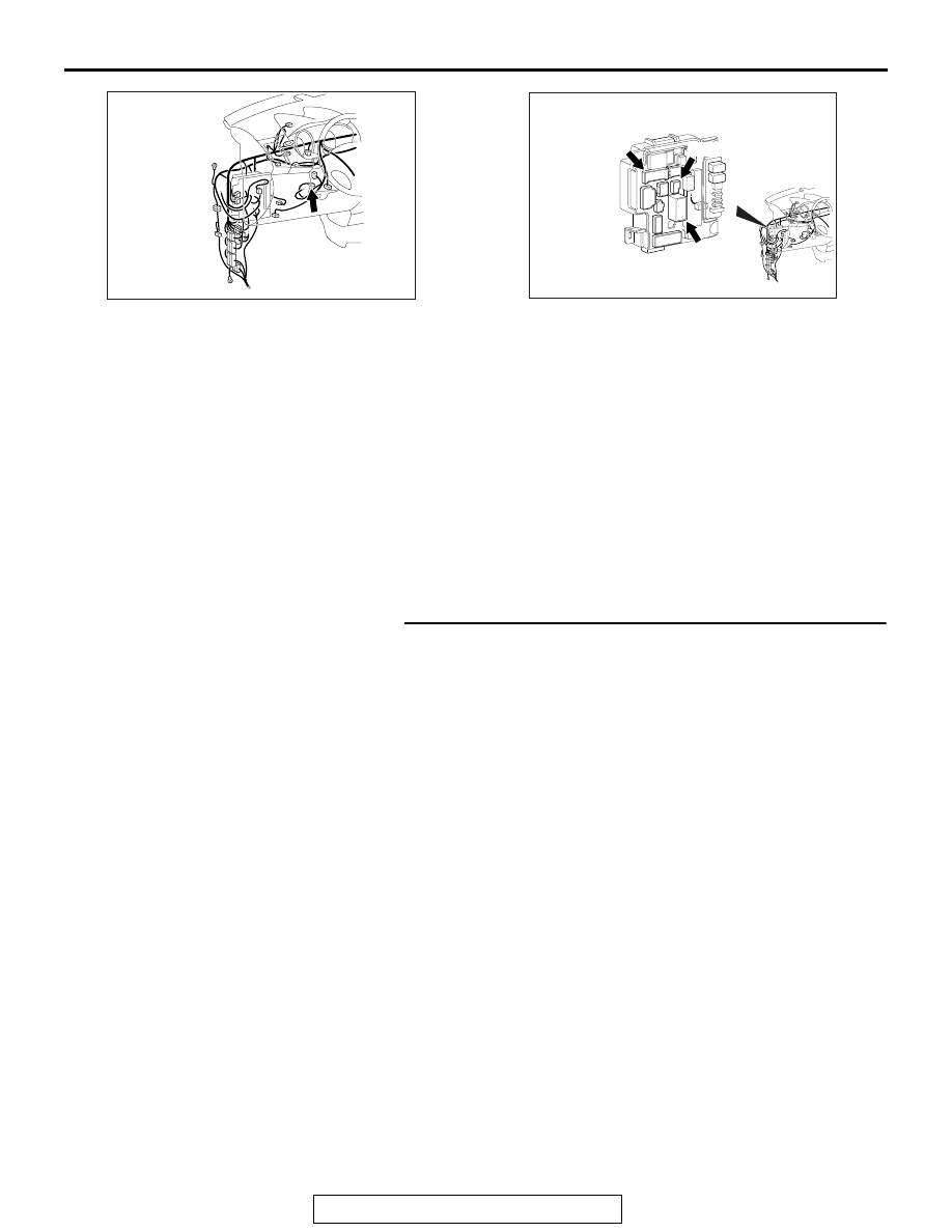
STEP 1. Check WCM connector C-29 and ETACS-ECU 
connector C-317 for loose, corroded or damaged 
terminals, or terminals pushed back in the connector.
Q: Is the WCM connector C-29 and ETACS-ECU connector 

C-317 in good condition?
YES : 
Go to Step 2.
NO :  Repair the defective connector.

AC702145 AI

Connector: C-29

AC701632 AI

Connectors: C-307, C-309, C-317

C-307 (B)

C-309 (B)

C-317

DIAGNOSIS

TSB Revision

WIRELESS CONTROL MODULE (WCM)

42C-88

STEP 2. Check the wiring harness between WCM 
connector C-29 (terminal No.6, 9) and the ETACS-ECU 
connector C-317 (terminal No.10, 5) for open circuit.
(1) Disconnect WCM connector C-29 and ETACS-ECU 

connector C-317, and check the wiring harness.

(2) Check the wiring harness between WCM connector C-29 

(terminal No.6) and ETACS-ECU connector C-317 (terminal 
No.10)

OK: Continuity exists (2 

Ω or less)

(3) Check the wiring harness between WCM connector C-29 

(terminal No.9) and ETACS-ECU connector C-317 (terminal 
No.5)

OK: Continuity exists (2 

Ω or less)

Q: Is the wiring harness between WCM connector C-29 and 

the ETACS-ECU connector C-317 in good condition?
YES : 
Go to Step 3.
NO :  Repair the wiring harness between WCM connector 

C-07 (terminal No.6, 9) and ETACS-ECU connector 
C-317 (terminal No.10, 5).

STEP 3. Check the wiring harness between the WCM 
connector C-29 (terminal No.7) and the ground for open 
circuit. 
(1) Disconnect the connector and measure the resistance at 

the wiring harness side.

(2) Turn the ignition switch to the ON position.
(3) Measure the resistance between terminal No.7 and the 

ground.

OK: Continuity exists (2 

Ω or less)

Q: Is the wiring harness between WCM connector C-29 and 

the ground in good condition?
YES : 
Go to Step 4.
NO :  Repair the wiring harness between WCM connector 

C-29 (terminal No.7) and ground.

AC709707EQ

Harness side: C-07

Harness side: C-317

AC709707ER

Harness side: C-07

Harness side: C-317

AC608812ED

Harness side: C-29

DIAGNOSIS

TSB Revision

WIRELESS CONTROL MODULE (WCM)

42C-89

STEP 4. Retest the system
Q: Does the abnormality in WCM power supply and ground 

circuits in good condition?
YES : 
The trouble can be an intermittent malfunction (Refer 

to GROUP 00, How to use 
Troubleshooting/inspection Service Points - How to 
Cope with Intermittent Malfunction 

P.00-15

).

NO :  Replace WCM and register the ID codes (Refer to 

P.42C-10

).

Inspection Procedure 5: Keyless entry system does not work.

CAUTION

Before replacing the ECU, ensure that the power supply 
circuit, the ground circuit and the communication circuit 
are normal.

.

OPERATION

The lock/unlock signals from the transmitter are received by 
WCM, and then sent to ETACS-ECU from WCM. When 
ETACS-ECU receives signals from the key reminder switch 
and all the door switches, ETACS-ECU actuates the keyless 
entry system.

.

PROBABLE CAUSES

• Malfunction of the key reminder switch

• Malfunction of the door switches

• Malfunction of keyless entry transmitter

• Malfunction of the WCM

• Malfunction of ETACS-ECU

• Damaged wiring harness and connectors

• Option coding information

DIAGNOSTIC PROCEDURE

Required Special Tools:

• MB991223: Harness Set

• MB992006: Extra Fine Probe

• MB991958: Scan Tool (M.U.T.-III Sub Assembly)

• MB991824: V.C.I.

• MB991827: M.U.T.-III USB Cable

• MB991910: M.U.T.-III Main Harness A

STEP 1. Scan tool (M.U.T.-III) CAN bus diagnostics
Use scan tool MB991958 (M.U.T.-III), diagnose the CAN bus 
lines.
Q: Is the CAN bus normal?

YES : Go to Step 2.
NO :  Repair the CAN bus line (Refer to GROUP 54C, CAN 

bus diagnostics chart 

P.54C-17

).

DIAGNOSIS

TSB Revision

WIRELESS CONTROL MODULE (WCM)

42C-90

STEP 2. Using scan tool MB991958, read the diagnostic 
trouble code.

CAUTION

To prevent damage to scan tool MB991958, always turn the 
ignition switch to the "LOCK" (OFF) position before con-
necting or disconnecting scan tool MB991958.
(1) Connect scan tool MB991958. Refer to "How to connect 

scan tool (M.U.T.-III) 

P.42C-7

."

(2) Turn the ignition switch to the "ON" position.
(3) Check whether the ETACS-ECU related DTC is set.
(4) Turn the ignition switch to the "LOCK" (OFF) position.
Q: Is the DTC set?

YES : Diagnose the ETACS-ECU. Refer to GROUP 54A, 

P.54A-733

.

NO :  Go to Step 3.

STEP 3. Check the power supply system
With the ignition switch in the LOCK (OFF) position, check if 
the following function operates normally:

• Headlight

• Hazard warning light

Q: Is the check result normal?

YES : Go to Step 4.
NO :  Refer to GROUP 54A, Malfunction of ETACS-ECU 

power supply circuit 

P.54A-783

.

STEP 4. Verify the central door locking system.
Q: Does the central door locking system work normally?

YES : Go to Step 5.
NO :  Refer to GROUP 42A, Trouble Symptom Chart 

P.42A-37

.

ZC501967

AC404789

AC701411AB

MB991824

MB991827

MB991910

Data link 
connector


Content   ..  1178  1179  1180  1181   ..