Content .. 1173 1174 1175 1176 ..
Mitsubishi Outlander GS45X. Manual - part 1175
DIAGNOSIS
TSB Revision
WIRELESS CONTROL MODULE (WCM)
42C-67
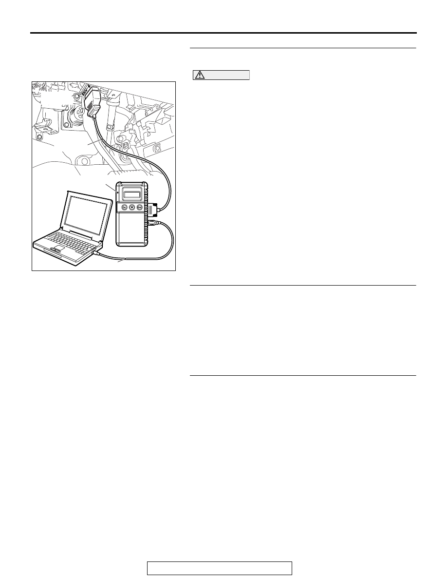
STEP 1. Using scan tool MB991958, diagnose the CAN bus
line
CAUTION
To prevent damage to scan tool MB991958, always turn the
ignition switch to the "LOCK" (OFF) position before con-
necting or disconnecting scan tool MB991958.
(1) Connect scan tool MB991958. Refer to "How to connect the
Scan Tool (M.U.T.-III)
(2) Turn the ignition switch to the "ON" position.
(3) Diagnose the CAN bus line.
(4) Turn the ignition switch to the "LOCK" (OFF) position.
Q: Is the CAN bus line found to be normal?
YES : Go to Step 2.
NO : Repair the CAN bus line. (Refer to GROUP 54C,
).
STEP 2. Using scan tool MB991958, read the A/C
diagnostic trouble code
Check if DTC is set to the A/C-ECU.
Q: Is the DTC set?
YES : Troubleshoot the A/C (Refer to GROUP 55A, Manual
A/C Diagnosis
or GROUP 55B, Auto A/C
NO : Go to Step 3.
STEP 3. Using scan tool MB991958, read the other system
diagnostic trouble code.
Check if DTC U0164 is set to the combination meter.
Q: Is the DTC set?
YES : Go to Step 4.
NO : Go to Step 5.
ZC501967
AC404789
AC701411AB
MB991824
MB991827
MB991910
Data link
connector