Mitsubishi Outlander GS45X. Manual - part 1146


  Index      Mitsubishi     Mitsubishi Outlander GS45X - service repair manual


Search            


Content   ..  1144  1145  1146  1147   ..


Mitsubishi Outlander GS45X. Manual - part 1146


DIAGNOSIS

TSB Revision

KEYLESS OPERATION SYSTEM (KOS)

42B-163

.

OPERATION

The receiver antenna module receives lock and 
unlock signals from the keyless operation key, and 
sends them to KOS-ECU, and further to 
ETACS-ECU. Also, when ETACS receives signals 
from the key reminder switch and all the door 
switches, ETACS-ECU judges them to activate the 
keyless entry function.

.

PROBABLE CAUSES

• Malfunction of CAN bus line

• Malfunction of the door switches

• Malfunction of the key reminder switch

• Malfunction of the receiver antenna module

• Malfunction of the keyless operation key

• Damaged wiring harness and connectors

• Malfunction of the KOS-ECU

• Malfunction of ETACS-ECU

DIAGNOSTIC PROCEDURE

Required Special Tools:

• MB991223: Harness Set

• MB992006: Extra Fine Probe

• MB991958: Scan Tool (M.U.T.-III Sub Assembly)

• MB991824: V.C.I.

• MB991827: M.U.T.-III USB Cable

• MB991910: M.U.T.-III Main Harness A
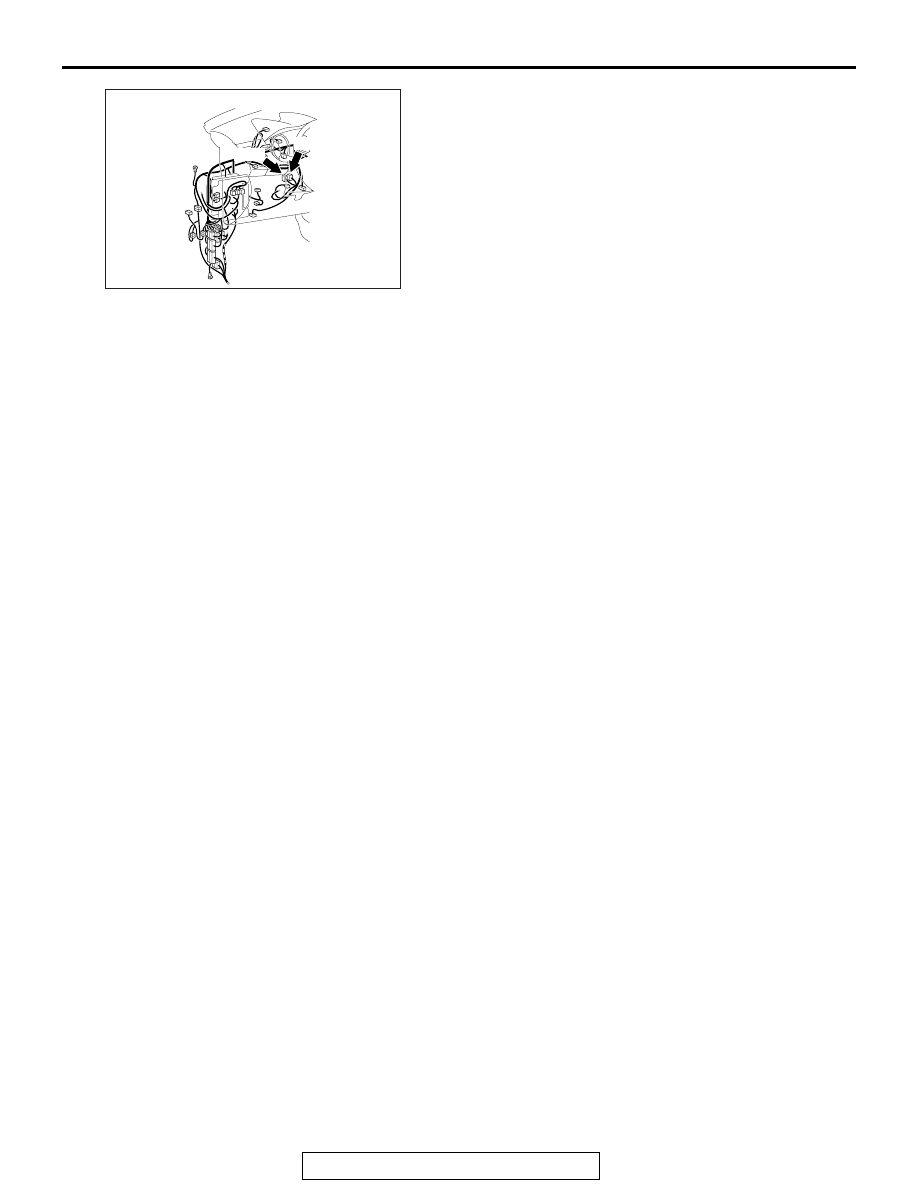
AC901075AK

Connectors: C-30, C-102

C-102

C-30

DIAGNOSIS

TSB Revision

KEYLESS OPERATION SYSTEM (KOS)

42B-164

STEP 1. Using scan tool MB991958, read CAN bus the 
diagnostic trouble code.

CAUTION

To prevent damage to scan tool MB991958, always turn the 
ignition switch to the "LOCK" (OFF) position before con-
necting or disconnecting scan tool MB991958.
(1) Connect scan tool MB991958. Refer to "How to connect 

scan tool (M.U.T.-III) 

P.42B-13

."

(2) Turn the ignition switch to the "ON" position.
(3) Check whether the CAN bus lines related DTC is set.
(4) Turn the ignition switch to the "LOCK" (OFF) position.
Q: Is the DTC set?

YES : Repair the CAN bus line (Refer to GROUP 54C, CAN 

bus diagnostics table 

P.54C-17

).

NO :  Go to Step 2.

ZC501967

AC404789

AC701411AB

MB991824

MB991827

MB991910

Data link 
connector

DIAGNOSIS

TSB Revision

KEYLESS OPERATION SYSTEM (KOS)

42B-165

STEP 2. Using scan tool MB991958, read the diagnostic 
trouble code.

CAUTION

To prevent damage to scan tool MB991958, always turn the 
ignition switch to the "LOCK" (OFF) position before con-
necting or disconnecting scan tool MB991958.
(1) Connect scan tool MB991958. Refer to "How to connect 

scan tool (M.U.T.-III) 

P.42B-13

."

(2) Turn the ignition switch to the "ON" position.
(3) Check whether the KOS-ECU related DTC is set.
(4) Turn the ignition switch to the "LOCK" (OFF) position.
Q: Is the DTC set?

YES : Diagnose the KOS-ECU. Refer to 

P.42B-35

.

NO :  Go to Step 3.

STEP 3. Check the power supply system
With the ignition switch in the LOCK (OFF) position, check if 
the following function operates normally:

• Headlights

• Hazard warning light

Q: Is the check result normal?

YES : Go to Step 4.
NO :  Refer to GROUP 54A 

− Malfunction of ETACS-ECU 

power supply circuit 

P.54A-783

.

ZC501967

AC404789

AC701411AB

MB991824

MB991827

MB991910

Data link 
connector

DIAGNOSIS

TSB Revision

KEYLESS OPERATION SYSTEM (KOS)

42B-166

STEP 4. Using scan tool MB991958, check data list.
Check the signals related to the keyless entry system opera-
tion.

CAUTION

To prevent damage to scan tool MB991958, always turn the 
ignition switch to the "LOCK" (OFF) position before con-
necting or disconnecting scan tool MB991958.
(1) Connect scan tool MB991958. Refer to "How to connect the 

Scan Tool (M.U.T.-III) 

P.42B-13

."

(2) Turn the ignition switch to the "ON" position.
(3) Check the ETACS data list.

• Turn the ignition switch to the LOCK (OFF) position.

• Close the driver's door.

• Close the passenger's door.

• Close the RH-side rear door.

• Close the LH-side rear door.

• Close the liftgate.

• Remove the ignition key from the ignition key cylinder.

(4) Turn the ignition switch to the "LOCK" (OFF) position.

OK: Normal condition is displayed.

Q: Is the check result normal?

YES (Normal conditions are displayed for all the items.) 

Go to Step 5.

NO (Normal condition is not displayed for item No. 254.) 

Refer to GROUP 54A, Inspection Procedure 2: 
ETACS-ECU does not receive any signal from the 
ignition switch (IG1) 

P.54A-789

.

NO (Normal condition is not displayed for item No. 256.) 

Refer to GROUP 54A, Inspection Procedure 5: 
ETACS-ECU does not receive any signal from the 
front door switch (LH) 

P.54A-804

.

NO (Normal condition is not displayed for item No. 257.) 

Refer to GROUP 54A, Inspection Procedure 6: 
ETACS-ECU does not receive any signal from the 
front door switch (RH) 

P.54A-802

.

Item No.

Item name

Normal 
condition

Item 254

IG voltage

Battery 
positive 
voltage

Item 256

Dr door ajar switch

Close

Item 257

As door ajar switch

Close

Item 258

RR door ajar switch Close

Item 259

RL door ajar switch

Close

Item 260

Trunk/gate trunk ajar 
switch

Close

Item 264

Handle lock switch

Key in 

→ Key 

out

ZC501967

AC404789

AC701411AB

MB991824

MB991827

MB991910

Data link 
connector


Content   ..  1144  1145  1146  1147   ..