Mitsubishi Outlander GS45X. Manual - part 1128


  Index      Mitsubishi     Mitsubishi Outlander GS45X - service repair manual


Search            


Content   ..  1126  1127  1128  1129   ..


Mitsubishi Outlander GS45X. Manual - part 1128


DIAGNOSIS

TSB Revision

KEYLESS OPERATION SYSTEM (KOS)

42B-91

DTC B2415: RA module power voltage

CAUTION

• If DTC B2415 is set, diagnose the CAN bus 

lines.

• When replacing the ECU, always check that 

the communication circuit is normal.

.

DTC SET CONDITION

If KOS-ECU detects an abnormality in power supply 
of the receiver antenna module, KOS-ECU sets DTC 
No. B2415.

.

TECHNICAL DESCRIPTION (COMMENT)

When the ignition switch is turned to ON, KOS-ECU 
transmits the signal to the receiver antenna module. 
The receiver antenna module transmits random 
numbers to the keyless operation key when it 
receives signals from KOS-ECU. If an open circuit or 
short to ground occurs on the wiring harness 
between KOS-ECU and receiver antenna module at 
this time, KOS-ECU determines that there is a prob-
lem.

.

TROUBLESHOOTING HINTS

• Malfunction of CAN bus line

• Damaged wiring harness and connectors

• Malfunction of the receiver antenna module

• Malfunction of KOS-ECU

DIAGNOSIS

Required Special Tools:

• MB991958: Scan Tool (M.U.T.-III Sub Assembly)

• MB991824: Vehicles Communication Interface (V.C.I.)

• MB991827: M.U.T.-III USB Cable

• MB991910: M.U.T.-III Main Harness A (Vehicles with 

CAN communication system)

ACA02751

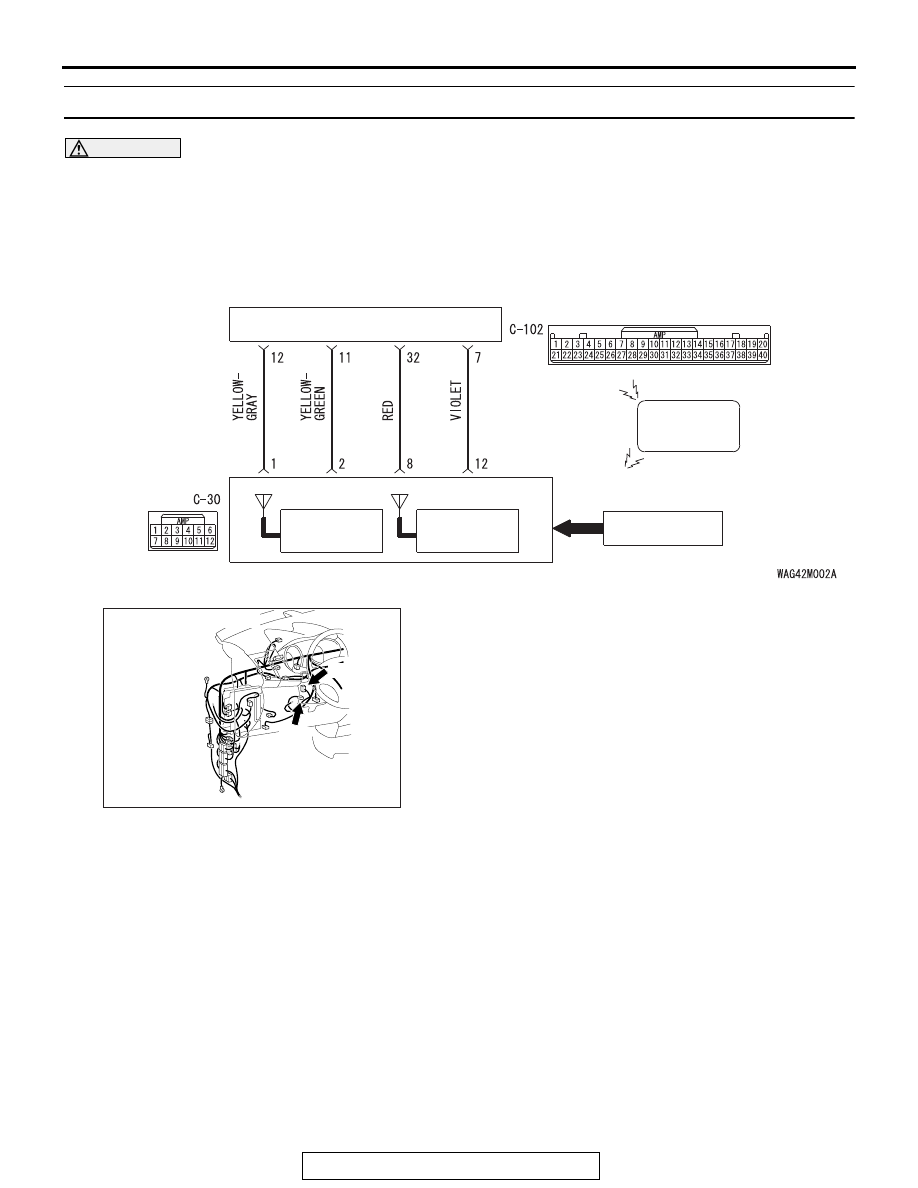
Receiver Antenna  Module and KOS-ECU Circuit

KEYLESS
OPERATION
KEY

RECEIVER ANTENNA
MODULE

KOS-ECU

TRANSPONDER

KEY ID

IMMOBILIZER 
ANTENNA

KEYLESS
ENTRY
RECEIVER

AB

AC702145AB

Connector: C-30, C-102

C-30

C-102

DIAGNOSIS

TSB Revision

KEYLESS OPERATION SYSTEM (KOS)

42B-92

STEP 1. Using scan tool MB991958, diagnose the CAN bus 
line.

CAUTION

To prevent damage to scan tool (MB991958), always turn 
the ignition switch to the "LOCK" (OFF) position before 
connecting or disconnecting scan tool (MB991958).
(1) Connect scan tool MB991958 to the data link connector.
(2) Turn the ignition switch to the "ON" position.
(3) Diagnose the CAN bus line.
(4) Turn the ignition switch to the "LOCK" (OFF) position.
Q: Is the CAN bus line found to be normal?

YES : Go to Step 2.
NO :  Repair the CAN bus line. (Refer to GROUP 54C, 

Diagnosis 

P.54C-17

).

STEP 2. Check receiver antenna module connector C-30 
and KOS-ECU connector C-102 for loose, corroded or 
damaged terminals, or terminals pushed back in the 
connector.
Q: Is the receiver antenna module connector C-30 and 

KOS-ECU connector C-102 in good condition?
YES : 
Go to Step 3.
NO :  Repair the defective connector.

STEP 3. Check the wiring harness between the receiver 
antenna module connector C-30 (terminal No. 8, 12) and 
the KOS-ECU connector C-102 (terminal No. 32, 7).

• Check the power supply and ground wires for open circuit 

or power supply wires for ground circuit.

Q: Is the wiring harness between receiver antenna module 

connector C-30 (terminal No. 8, 12) and the KOS-ECU 
connector C-102 (terminal No. 32, 7) in good condition?
YES : 
Go to Step 4.
NO :  The wiring harness may be damaged or the 

connector(s) may have loose, corroded or damaged 
terminals, or terminals pushed back in the connector. 
Repair the wiring harness as necessary.

ZC501967

AC404789

AC701411AB

MB991824

MB991827

MB991910

Data link 
connector

DIAGNOSIS

TSB Revision

KEYLESS OPERATION SYSTEM (KOS)

42B-93

STEP 4. Replace the receiver antenna module, and check 
whether the diagnostic trouble code is reset.
(1) Turn the ignition switch from the "LOCK" (OFF) position to 

the "ON" position.

(2) Check if the DTC is set.
Q: Is the DTC set?

YES : Replace KOS-ECU and register the ID codes. (Refer 

to 

P.42B-15

.)

NO :  The trouble can be an intermittent malfunction (Refer 

to GROUP 00 

− How to use 

Troubleshooting/inspection Service Points 

− How to 

Cope with Intermittent Malfunction 

P.00-15

).

DTC B2416: ECU internal error

.

DTC SET CONDITION

KOS-ECU sets DTC B2416 when it determines itself 
to be in abnormal status.

.

TECHNICAL DESCRIPTION (COMMENT)

KOS-ECU determines that the abnormality is 
present, if the data abnormality is found when the 
ignition switch is turned ON and then EEPROM is 
written.

.

TROUBLESHOOTING HINTS

Malfunction of KOS-ECU

DIAGNOSIS

Required Special Tools:

• MB991958: Scan Tool (M.U.T.-III Sub Assembly)

• MB991824: Vehicles Communication Interface (V.C.I.)

• MB991827: M.U.T.-III USB Cable

• MB991910: M.U.T.-III Main Harness A (Vehicles with 

CAN communication system)

DIAGNOSIS

TSB Revision

KEYLESS OPERATION SYSTEM (KOS)

42B-94

Recheck for diagnostic trouble code.
Check again if the DTC is set to the KOS-ECU.

CAUTION

To prevent damage to scan tool (MB991958), always turn 
the ignition switch to the "LOCK" (OFF) position before 
connecting or disconnecting scan tool (MB991958).
(1) Connect scan tool MB991958 to the data link connector.
(2) Erase the DTC.
(3) Turn the ignition switch from "LOCK" (OFF) position to "ON" 

position.

(4) Check if DTC is set.
(5) Turn the ignition switch to the "LOCK" (OFF) position.
Q: Is the DTC set?

YES : Replace KOS-ECU and register the ID codes. (Refer 

to 

P.42B-15

.)

NO :  The trouble can be an intermittent malfunction (Refer 

to GROUP 00 

− How to use 

Troubleshooting/inspection Service Points 

− How to 

Cope with Intermittent Malfunction 

P.00-15

).

DTC C1608: EEPROM Error

CAUTION

If there is any problem in the CAN bus lines, an incorrect 
diagnostic trouble code may be set. Prior to this diagno-
sis, diagnose the CAN bus lines (Refer to GROUP 54C, 
Trouble code diagnosis 

P.54C-17

).

.

DTC SET CONDITION

KOS incorporates EEPROM (nonvolatile memory), and that 
EEPROM stores the TPMS, KOS and immobilizer information. 
When the data in EEPROM is failed, this code is set.

.

TROUBLESHOOTING HINTS

The most likely causes for this DTC to set are:

• Damaged wiring harness and connector

• Malfunction of KOS-ECU

DIAGNOSIS

Required Special Tools:

• MB991958: Scan Tool (M.U.T.-III Sub Assembly)

• MB991824: Vehicle Communication Interface (V.C.I.)

• MB991827: M.U.T.-III USB Cable

• MB991910: M.U.T.-III Main Harness A 

ZC501967

AC404789

AC701411AB

MB991824

MB991827

MB991910

Data link 
connector


Content   ..  1126  1127  1128  1129   ..