Mitsubishi Outlander GS45X. Manual - part 1122


  Index      Mitsubishi     Mitsubishi Outlander GS45X - service repair manual


Search            


Content   ..  1120  1121  1122  1123   ..


Mitsubishi Outlander GS45X. Manual - part 1122


DIAGNOSIS

TSB Revision

KEYLESS OPERATION SYSTEM (KOS)

42B-67

.

DTC SET CONDITION

When the ignition push switch is pressed, the steer-
ing lock unit communicates with KOS-ECU to unlock 
the IG knob. If the steering lock unit communication 
error (no response) occurs at this time, the DTC is 
set.

.

TECHNICAL DESCRIPTION (COMMENT)

When the IG knob unlock communication is per-
formed by pressing the ignition push switch, if the 
steering lock unit communication error (no response) 
occurs, the steering lock unit is judged as abnormal.

.

TROUBLESHOOTING HINTS

• Malfunction of the key reminder switch (inte-

grated into the steering lock unit)

• Wiring harness or connector failure of CAN bus 

line

• Malfunction of the KOS-ECU

DIAGNOSIS

Required Special Tools:

• MB991958: Scan Tool (M.U.T.-III Sub Assembly)

• MB991824: Vehicles Communication Interface (V.C.I.)

• MB991827: M.U.T.-III USB Cable

• MB991910: M.U.T.-III Main Harness A (Vehicles with 

CAN communication system)
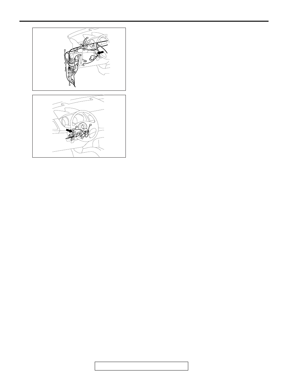
AC702145

Connector: C-102

AB

AC702217 AB

Connector: C-211

DIAGNOSIS

TSB Revision

KEYLESS OPERATION SYSTEM (KOS)

42B-68

STEP 1. Using scan tool MB991958, diagnose the CAN bus 
line.

CAUTION

To prevent damage to scan tool (MB991958), always turn 
the ignition switch to the "LOCK" (OFF) position before 
connecting or disconnecting scan tool (MB991958).
(1) Connect scan tool MB991958 to the data link connector.
(2) Turn the ignition switch to the "ON" position.
(3) Diagnose the CAN bus line.
(4) Turn the ignition switch to the "LOCK" (OFF) position.
Q: Is the CAN bus line found to be normal?

YES : Go to Step 2.
NO :  Repair the CAN bus line. (Refer to GROUP 54C 

− 

Diagnosis 

P.54C-17

).

STEP 2. Check key reminder switch connector C-211 and 
KOS-ECU connector C-102 for loose, corroded or 
damaged terminals, or terminals pushed back in the 
connector.
Q: Is the key reminder switch connector C-211 and 

KOS-ECU connector C-102 in good condition?
YES : 
Go to Step 3.
NO :  Repair the defective connector.

STEP 3. Check the wiring harness between the key 
reminder switch connector C-211 (terminal No. 12, 9, 11) 
and the KOS-ECU connector C-102 (terminal No. 4, 5, 31).

• Check the signal lines for open circuit and short circuit.

Q: Is the wiring harness between key reminder switch 

connector C-211 (terminal No. 12, 9, 11) and the 
KOS-ECU connector C-102 (terminal No. 4, 5, 31) in 
good condition?
YES : 
Go to Step 4.
NO :  The wiring harness may be damaged or the 

connector(s) may have loose, corroded or damaged 
terminals, or terminals pushed back in the connector. 
Repair the wiring harness as necessary.

ZC501967

AC404789

AC701411AB

MB991824

MB991827

MB991910

Data link 
connector

DIAGNOSIS

TSB Revision

KEYLESS OPERATION SYSTEM (KOS)

42B-69

STEP 4. Replace the key reminder switch, and check 
whether the diagnostic trouble code is reset.
(1) Erase the DTC.
(2) Turn the ignition switch from the "LOCK" (OFF) position to 

the "ON" position.

(3) Check if the DTC is set.
Q: Is the DTC set?

YES : Replace KOS-ECU and register the ID codes. (Refer 

to 

P.42B-15

.)

NO :  The trouble can be an intermittent malfunction (Refer 

to GROUP 00 

− How to use 

Troubleshooting/inspection Service Points 

− How to 

Cope with Intermittent Malfunction 

P.00-15

).

DTC B240A DR side antenna(outdoor) open

CAUTION

When replacing the ECU, always check that the 
communication circuit is normal.

ACA02755

KOS-ECU

KEYLESS 
OPERATION 
KEY

OUTSIDE TRANSMISSION 
ANTENNA ASSEMBLY 
(DRIVER'S SIDE)

SKY  BLUE

SKY  BLUE

SKY  BLUE

RED- BLA

CK

RED- BLA

CK

RED- BLA

CK

RED- YELLO

W

RED-YELLO

W

 Outside Transmission Antenna assembly (Driver's Side) Circuit

AB

DIAGNOSIS

TSB Revision

KEYLESS OPERATION SYSTEM (KOS)

42B-70

.

DIAGNOSTIC FUNCTION

If an open circuit is detected in the outside transmis-
sion antenna assembly (driver's side), the diagnostic 
trouble code is set.

.

JUDGMENT CRITERIA

When the ignition push switch is pressed, or when 
the antenna open circuit detection request is 
received from the diagnosis function, the failure is 
detected.

.

PROBABLE CAUSES

• Malfunction of the outside transmission antenna 

assembly (driver's side)

• Malfunction of the KOS-ECU

• Damaged wiring harness and connectors

DIAGNOSTIC PROCEDURE

STEP 1. Check KOS-ECU connector C-102 and outside 
transmission antenna assembly (driver's side) connector 
D-131 for loose, corroded or damaged terminals, or 
terminals pushed back in the connector.
Q: Are KOS-ECU connector C-102 and outside 

transmission antenna assembly (driver's side) 
connector D-131 in good condition?
YES : 
Go to Step 2.
NO :  Repair or replace the damaged component(s). Refer 

to GROUP 00E, Harness Connector Inspection 

P.00E-2

.

AC901076AG

Connector: C-22

AC901075AF

Connectors: C-32, C-102

C-32

C-102

AC901080AJ

Connector: D-131


Content   ..  1120  1121  1122  1123   ..