Mitsubishi Outlander GS45X. Manual - part 1093


  Index      Mitsubishi     Mitsubishi Outlander GS45X - service repair manual


Search            


Content   ..  1091  1092  1093  1094   ..


Mitsubishi Outlander GS45X. Manual - part 1093


LIFTGATE

TSB Revision

BODY

42A-175

INSTALLATION SERVICE POINT

.

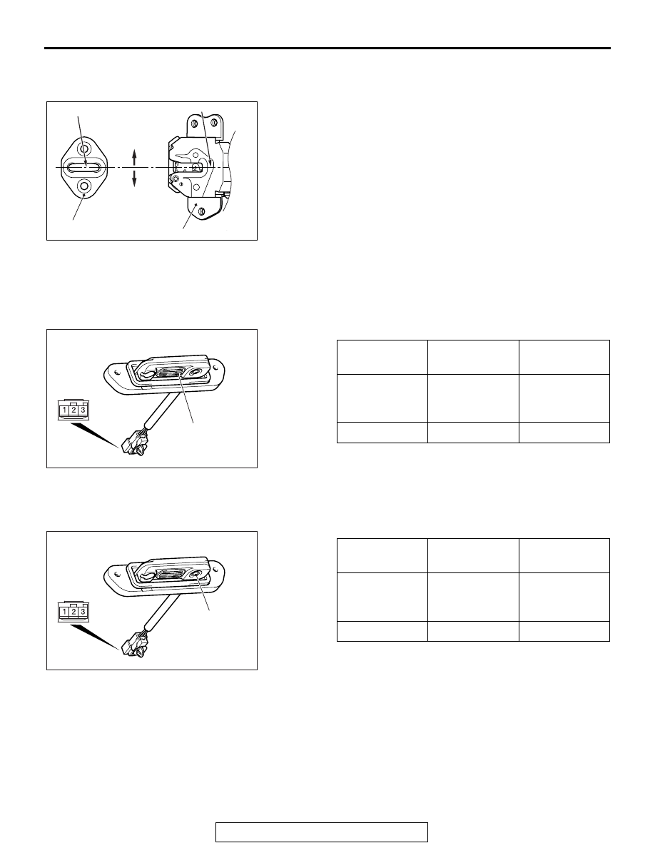
>>A<< STRIKER INSTALLATION

Install the striker so that the striker center does not deviate 
more than 

±1.5 mm (0.06 inch) from the latch center.

INSPECTION

M1424002100278

LIFTGATE LOCK RELEASE HANDLE (LIFTGATE 
OPEN SWITCH) CHECK

<VEHICLES WITH KOS>

LIFTGATE LOCK RELEASE HANDLE (LIFTGATE 
LOCK SWITCH) CHECK <VEHICLES WITH KOS>

AC703419AB

+1.5 mm 

(0.06 in)

-1.5 mm 

(0.06 in)

Striker center

Striker

Latch center

Latch

Switch 
position

Terminal 
number

Normal value

Push (open)

− 2 

Continuity 
exists (2 

Ω or 

less)

Release

− 2 

No continuity

ACA00837AF

Open switch

Switch 
position

Terminal 
number

Normal value

Push (lock)

− 3 

Continuity 
exists (2 

Ω or 

less)

Release

− 3 

No continuity

ACA00837AE

Lock switch

LIFTGATE

TSB Revision

BODY

42A-176

LIFTGATE LOCK ACTUATOR CHECK

LIFTGATE LATCH SWITCH CHECK

Lever 
position

Battery 
connection

Lever operation

At the 
"SET" 
position

• Connect 

terminal 2 to 
negative battery 
terminal.

• Connect 

terminal 1 to 
positive battery 
terminal.

Lever moves 
from "SET" to 
"OPEN" position.

AC302760AG

Set

Lever

Open

Claw position

Terminal 
number

Normal value

Unlatch (ON)/ 
Half-latch (ON)

− Ground

Continuity 
exists (2 

Ω or 

less)

Full-latch (OFF) 1 

− Ground

No continuity

AC905470AC

Unlatch 
(ON)

Half-latch 
(ON)

Full-latch 
(OFF)

1

LIFTGATE

TSB Revision

BODY

42A-177

REMOVAL AND INSTALLATION <LIFTGATE LOWER>

M1424001700772

INSTALLATION SERVICE POINTS

.

>>A<< LIFTGATE WEATHERSTRIP INSTALLA-
TION

1. The marking on the liftgate weatherstrip should be 

positioned at the center of the liftgate lower.

2. Install the weatherstrip according to the order shown in the 

figure.

3. Install the weatherstrip according to the direction shown by 

the arrow in the figure.

.

Post-installation operation
• Liftgate alignment (Refer to 

P.42A-168

).

AC713420

1

2

4

3

4

5

AB

20 ± 5 N·m
15 ± 3 ft-lb

2.5 ± 0.5 N·m
23 ± 4 in-lb

7.0 ± 2.0 N·m
43 ± 18 in-lb

7.0 ± 2.0 N·m
43 ± 18 in-lb

2.5 ± 0.5 N·m
23 ± 4 in-lb

:Sectional view of 
 clip position

Liftgate lock release handle knob 
removal 

1.

Liftgate lock release handle knob
Striker removal steps 

1.

Liftgate lock release handle knob

Liftgate lower trim (Refer to 
GROUP 52A, Liftgate Trim 

P.52A-14

.)

>>B<<

2.

Striker

Liftgate latch removal steps 

1.

Liftgate lock release handle knob

Liftgate lower trim (Refer to 
GROUP 52A, Liftgate Trim 

P.52A-14

.)

3.

Liftgate handle controller

4.

Liftgate latch
Liftgate weatherstrip removal 

>>A<<

5.

Liftgate weatherstrip

AC703421AB

1

1

2

2

Positioning mark

LIFTGATE

TSB Revision

BODY

42A-178

>>B<< STRIKER INSTALLATION

Install the striker so that the striker center does not deviate 
more than 

±1.5 mm (0.06 in) from the latch center.

AC703419AB

+1.5 mm 

(0.06 in)

-1.5 mm 

(0.06 in)

Striker center

Striker

Latch center

Latch


Content   ..  1091  1092  1093  1094   ..