Content .. 1030 1031 1032 1033 ..
Mitsubishi Outlander GS45X. Manual - part 1032
AUTOMATIC A/C DIAGNOSIS
TSB Revision
AUTOMATIC AIR CONDITIONING
55B-19
31
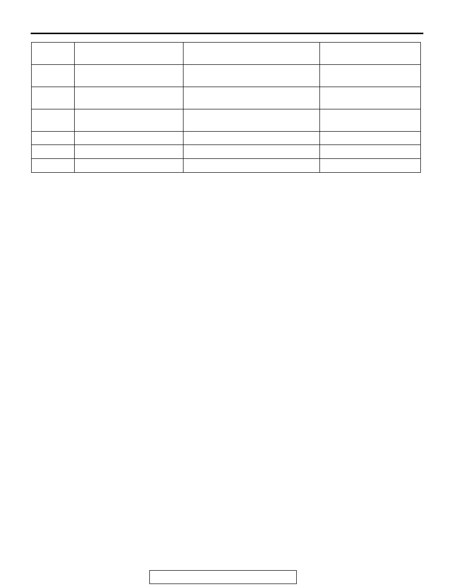
Air outlet changeover
damper motor
−
−
32
Air outlet changeover
damper motor
−
−
33
Air outlet changeover
damper motor
−
−
34
Air mix damper motor
−
−
35
Air mix damper motor
−
−
36
Air mix damper motor
−
−
Terminal
No.
Check items
Check conditions
Normal conditions